
User Manual

Asset-Link 250 User Manual July 19, 2004
970-00047 Rev. 1.2
CSI Wireless©2004 Specifications subject to change without notice Page 5-1
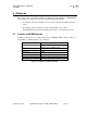
5 GPS Connector Specifications
The GPS connector is a standard female FAKRA SMB connector. The shell of the
connector is connected to the Asset-Link chassis. The center pin of the connector is
for the GPS receiver input and output at 50 ohms nominal impedance.
The GPS connector is designed to be connected to an antenna with an integral Low
Noise Amplifier (LNA) for GPS signals.
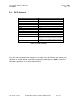
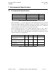
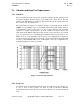
5.1.1 GPS Connector
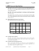
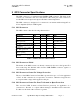
The GPS connector has the following characteristics:
Parameter Min Nominal
Max Units
1574 MHz Impedance 50 ohms
1574 MHz Return Loss 6 12 Inf dB
D.C Bias
(GPS Operational)
3.0 3.3 3.6 Volts
10mA<Ibias<40mA
Current Sourcing 10 20 40 mA
D.C. Bias to Open Circuit GPS
not operating
-0.2 0 0.2 volts
Impedance to bias voltage at
D.C., GPS Operational
15 ohms
Imp
edance to Ground at D.C.
GPS not operating
20K 25K 30K ohms
Maximum RF voltage applied
externally
-30 dBm
Table 5-1 GPS Connector Characteristics
5.1.2 GPS Connector Shield
The shield on the GPS connector is directly connected to the Asset-Link ground. For
best results keep the shielded cable from the SMB FAKRA connector against or
surrounded by the metal frame.
5.1.3 GPS Connector Center Pin Voltage Protection
The Asset-Link GPS Connector Center Pin is protected for up to +/-5 volts application
of D.C. As this connection is not expected to be used for vehicular voltage I/O it is
not expected that voltage will be applied to this pin.
5.1.4 GPS Connector Center Pin Short To Ground or Open Protection
The Asset-Link GPS Connector Center Pin has protection for application of a
connection to “Ground” or a “Open”without damage to the GPS receiver electronics.
For this test, the shell of the connector is ground.