
User Manual

Asset-Link 250 User Manual July 19, 2004
970-00047 Rev. 1.2
CSI Wireless©2004 Specifications subject to change without notice Page 4-1
4 AMPS Connector Specifications
The cellular connector is either a standard right angle male FAKRA SMB connector.
The shell of the connector is connected to the Asset-Link ground. The center pin of
the connector is for the AMPS Cellular Class III transceiver input and output at 50
ohms nominal impedance.
The AMPs cellular connector is designed to be connected to an antenna of less than 3
dBd gain, to meet safety standards. Refer to the warnings in the cellular antenna
accessories section.
The cellular module is selected by a passive relay contact internal to the T4000. When
one module is connected, the other module is disconnected. The relay is a latching
type, so it will remain in the position for the last selected radio module even when all
power is removed.
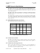
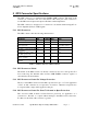
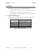
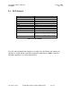
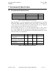
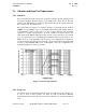
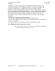
4.1.1 AMPs/GSM Cellular Interface Specification
The cellular interface has the following characteristics:
Parameter Min Nominal Max Units
825-894 MHz &
Impedance
30 50 85 Ohms
825-
894 MHz Return
Loss
12 15 Inf DB
Maximum RF
voltage applied 850
to 900 MHz
-- -- -30 DBm
Maximum RF signal
available 820 to 850
MHz
-- -- 33 DBm
Impedance to
Ground at D.C.
10K 10M Inf Ohms
Table 4-1 Cellular Interface Characteristics
4.1.2 Cellular Connector Shield
The shield on the cellular connector is directly connected to the Asset-Link ground.
For best results use keep the shielded cable from the cellular connector against or
surrounded by the metal frame.
4.1.3 Cellular Center Pin Voltage Protection
The Asset-Link cellular Center Pin is protected for up to +/-36 volts application of
D.C. As this connection is not expected to be used for vehicular voltage I/O it is not
expected that voltage will be applied to this pin.