
User Manual
Asset-Link 250 User Manual July 19, 2004
970-00047 Rev. 1.2
CSI Wireless©2004 Specifications subject to change without notice Page 3-6
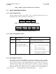
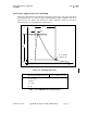
3.3 Relay Driver Specifications
These output pins are designed to operate an automotive relay similar to Bosch
Automotive relay, type VF4-45F11-S01, or electrical equivalent.
The relay coil positive is to be connected to the vehicle positive through a fused
connection, and an integral flyback diode on the relay coil is recommended.
The relay coil negative is to be connected to these relay driver outputs, which will
give a low impedance to “Ground” when activated.
3.4 Analog to Digital Converter Inputs
The four ADC input lines are high impedance to “Ground”. Analog Inputs are input
to the FCP through the PIC I/O processors built in 10-bit A-D (analog to digital)
converter, which reads a voltage, this value is available when there is greater than 8V
available to the Asset-Link .
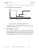
3.5 PIC Serial Data Output
This I/O line is a high impedance output with a logic voltage coming from the Asset-
Link . Serial Output is controlled by the FCP, which gives either a “logic high” or a
“logic low” that is available when there is a greater than 8V available to the Asset-
Link .
3.6 PIC Serial Data Input
This I/O line is a high impedance input with a logic voltage coming from the device
supplying the Asset-Link with serial data. Serial Input is monitored by the FCP, when
there is a Power Supply available to the Asset-Link and it is either in the Active or
Full Power mode.