
User Manual
Asset-Link 250 User Manual July 19, 2004
970-00047 Rev. 1.2
CSI Wireless©2004 Specifications subject to change without notice Page 2-10
• GPS (fix updates, constraint regions, constraint groups)
• Cellular module (Standby for CSD connection or MicroBurst® messages
transmission and receiving)
• Check power supply voltage
• Check digital, analog and LCP inputs.
• Data Log and Batch Processor
• Event Monitor and Exception Handler
• Action Scheduler
• Action Processor
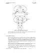
A typical exception configuration might be to use a Boolean combination of:
• One digital input connected to engine ignition (key on indicator)
• One analog input connected to oil pressure (engine running indicator)
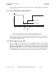
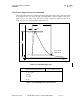
2.4.3 Power Off Mode
The Power-Off mode is the lowest power consumption mode.
Under most configurations when using Microburst for data communications, it is
advisable that the device be configured to issue a Reverse Control Channel (RECC)
status message before entry into the Power-Off mode. The status message will alert
the host that the client device has entered the Power-Off mode and thus can no longer
receive Forward Control Channel (FOCC) messages. In a usual vehicle application,
the device shall remain in the Power-Off mode until awakened by either detecting the
vehicle’s switched ignition circuit turned on via one of the analog or digital input, or
upon sensing other appropriate “wake-up” activity.
For GSM operations the SMS messages will be stored for the configured period of
time (normally 24 hours).
2.4.4 Connection and Configuration
One challenge remains for the application provider/developer of the Asset-Link
configuration. That is while fulfilling all the necessary application features, reducing
the consumption of asset power (vehicle battery) and backup battery (when installed)
to yet allow the Asset-Link to run and connect to the network for as long as possible.
This can be achieved by a careful design of the transition conditions of operating
modes, which could include I/O inputs, exceptions, schedules etc.
2.5 Power Management
The Power management provides for the powering of all components within the
Asset-Link from the V
IN
_POS and V
IN
_NEG pins on the DB-25 connector. The
supply design is for a 12-volt or 24-volt vehicular system, and this includes: