
User Manual


Asset-Link 250 User Manual July 19, 2004
970-00047 Rev. 1.2
CSI Wireless©2004 Specifications subject to change without notice Page 2-6
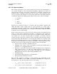
I/O timer Configurable between 2 s to 65535 s
Ears-On Timer Configurable between 2 s to 65535 s
GPS warm-up timer Configurable between 0 to 255s
GPS fix duration timer Configurable between 0 to 65535s
I/O inputs poll rate (Power off mode) Configurable 2 to 63 s
Note: nominal supply voltage range should be 8-36V DC.
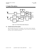
2.4.2.1 FCP Sleep Mode Operation
In the Sleep Mode, the only section doing any processing is the Real Time Clock
(RTC). The processor periodically enters the “Activity Check” state from the Sleep
Mode. The interval for entry to the Activity Check state is configurable from 2 to 63
seconds and it is recommended 10-30s is used. In this mode the total power
consumption is nominally about 35uA.
In addition to the RTC, the I/O controller hardware is able to detect changes
(interrupts) on the serial port on the 25 pin connector (pin 9), three of the eight digital
GPIOs (GPIO 1, 2 & 3 – pins 2,15 & 3, respectively) and on the supply. The Asset-
Link can be made to enter “Activity Check” sub-mode with activity on these lines.
When doing the Activity Check, the four analog inputs, the power supply voltage;
and the Schedules and Elapsed timers are also checked. If any of these activities have
events that require processing, the Asset-Link will transition to Active mode.
When the Asset-Link enters Active mode, the two GPS timers, the ears-on timer and
the I/O timer are set, according to the configuration and the trigger, and begin to
count down to the time when Sleep mode will be entered.
Under most configurations when using SMS for data communications, it is advisable
that the device be configured to issue a status message before entry into the Power-
Off mode. The status message will alert the host that the client device has entered the
Power-Off mode and thus can no longer respond. Many applications do the same for
entry into the Sleep mode, this alerts the service provider that the device can no
longer receive messages. In a usual vehicle application, the device shall remain in the
Sleep mode until awakened by either detecting the vehicle’s switched ignition circuit
turned on via one of the analog input, or upon sensing appropriate “wake-up” activity
on one of the three ‘wake’ digital GPIOs.
The following functions are disabled while the FCP is in the Sleep mode:
• GPS Receiver
• Cellular and GSM module
• Data Log and Batch Processor
• Timer (except elapsed timer) and Exception Handler
• Action Processor