
User's Manual

CSI-Wireless AssetLink 200 Installation and Operating Instructions
Revision 1.0 Page 6 1/2/2002
2.3 External I/O
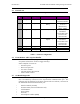
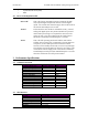
The seven I/O connections of the AssetLink 200 are configured as follows:
Line
#
Designation Type Function Signal Chracterics
1
Output Relay Driver Doors Unlock Relay Pulse active low, 1
second maximum
2
Output Relay Driver Starter Enable/disable
Relay
Level, stays high
or low as
determined by
MIN3 / MIN4
3
Input Digital Crash Sensor, Low Impact Active low,
minimum 1
second. Rise time
less than 150
microseconds
4
Input Digital Crash Sensor, High
Impact
Active low,
minimum 1
second. Rise time
less than 150
microseconds
5
Output Digital Future Assignment
6
Output Digital Future Assignment
7
Input Analogue Future Assignment
Table 3 – I/O Port Configuration
2.4 Event Monitor and Exception Handler
The AssetLink 200 unit is programmed to recognize a number of events as
exceptions and use these events to trigger action(s).
Some examples of events are:
• Excessive speed.
• Door lock open/close
• Geo-fence violation
• The GPS antenna disconnected.
• Vehicle alarm violated
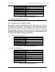
2.5 On Board Diagnostics
The AssetLink 200 incorporates on board diagnostics and troubleshooting support
that is accessible by connection to the asynchronous communications port. The
following will be displayed in the Asset Vision Link test software, connected to
the AssetLink 200 via the RS232 serial port.
• GPS fix attained (Yes/No)
• Antenna Status (Connected/disconnected)
• Cellular RSSI
• Asset voltage
• Asset ID
• Internal phone number (MIN)