
User's Manual

CSI-Wireless AssetLink 200 Installation and Operating Instructions
Revision 1.0 Page 10 1/2/2002
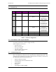
RELAY DRIVER:
Output Impedance
0 ohm 3 ohm
Input High Voltage for less
than 1 mA draw
0V 32V
Reverse Voltage at 1 mA draw
0V -2V
Table 13 – Analogue & Digital Lines Specifications
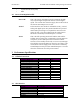
3.5.3 External Connector Pin Assignments
Connector on AssetLink 200: Molex 53259-1310 or equivalent
Mating connector, for customer-supplied cable harness: Molex 51067-1300 or equivalent
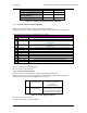
The external I/O connector pin assignments are as follows:
Pin
Description Notes
1
Relay Driver 1 Connects relay coil to ground, other side of relay coil goes to supply positive.
2
Relay Driver 2 Connects relay coil to ground, other side of relay coil goes to supply positive.
3
Digital Output 1 0 and 5 volt logic signal with 2 KOhm series impedance driven from
AssetLink 200
4
Digital Output 2 0 and 5 volt logic signal with 2 KOhm series impedance driven from
AssetLink 200
5
Digital Input 1 0 and 5 volt logic signal with 300 KOhm to ground as input to AssetLink 200
6
Digital Input 2 0 and 5 volt logic signal with 300 KOhm to ground as input to AssetLink 200
7
Analog Input Input for measurement, 0 to 38 volts
8
Ground Connects to chassis of AssetLink 200
9
Serial Output Signal from AssetLink 200 to Computer
10
Serial Input Signal from Computer to AssetLink 200
11
Reserved Reserved for factory use
12
5 Volt Reference 5 volts with 2 KOhm series impedance, for reference use
13
Battery Voltage For measurement only, 0 to 38 volts range.
Table 14 - External Signal Connector
Pin 1 is next to larger connector (TNC)
Pin 13 is next to 2 pin connector
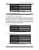
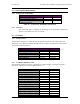
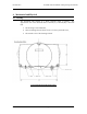
3.5.4 Power Lead Assignments
Power Connector on AssetLink 200: Molex 53259-0210 or equivalent
Mating connector, for customer-supplied cable harness: Molex 51067-0200 or equivalent
The AssetLink 200 power lead assignments are as follows:
1 Supply Battery
Voltage Positive
Power input to AssetLink 200, 8
to 36 volts, 2 amp fused
externally,
internally protected.
2 Supply Battery
Voltage Negative
Power input to AssetLink 200,
battery negative with protection
for current to chassis, connected
to chassis with low impedance.
Table 15 - Power Supply Lead Use.
Pin 1 is next to 13 pin connector
Pin 2 is next to smaller connector (SMA).