
User`s guide


Table Of Contents
- Copyrights and Trademarks
- Disclaimer
- Welcome to NetVision
- Common / Daily Tasks
- 5 Starting your Software and Logging In
- 6 Alarm / Reporting Features and 'Chatting'
- 7 Playing or Downloading Video Recordings
- 7.1 Overview--Types of Playback
- 7.2 Playback--Technical Details
- 7.3 Synchronized Playback (v2.3 SP2)
- 7.4 Video Search (v2.3 SP2)
- 7.5 Searching for Motion
- 7.6 Working with the Playback Screen
- 7.7 Viewing and Printing 'Snapshots'
- 7.8 Working with the File List
- 7.9 Quad Playback
- 7.10 Server Management--Identifying Remote Servers for Playback
- 8 Viewing Live Cameras
- 9 Recording Camera-Views
- System Administration and Maintenance
- 10 Tasks Applicable to Remote Stations and the Video Server
- 10.1 PC Date and Time
- 10.2 Checking your Software Version
- 10.3 Introduction to Video File Management (Filekeeping and Housekeeping)
- 10.4 To Allow Using a Blank CD (Roxio - Easy CD Creator 5 basic with DirectCD)
- 10.5 Filekeeping (v2.3 SP2)
- 10.6 Housekeeping
- 10.7 Automatic Video File Management (Self Housekeeping)
- 11 Tasks Performed at the Video Server Only
- 10 Tasks Applicable to Remote Stations and the Video Server
- System Configuration
- Software Installation and Network Set Up
- 19 PC Requirements
- 20 Software Installation or Upgrade
- 21 Network and Connectivity Issues
- 21.1 General Network Requirements
- 21.2 IP Addressing on the Network
- 21.3 Network Services
- 21.4 Network Ports
- 21.5 To Connect via the Internet
- 21.6 Remote User Permissions
- 21.7 For Remote Viewing, Recording, Playback, and/or Audio Monitoring
- 21.8 For Alarm Alerts
- 21.9 For E-Mail Alerts
- 21.10 Windows Dial-Up Networking Connection (i.e., not via the Internet)
- 21.11 Network Usage
- Reference Topics
- 22 Using the Small Remote Module
- 23 Remote Configuration
- 24 The WatchDog Feature
- 25 Hardware Reference
- 26 Troubleshooting
- 27 Using the ATM Interface Option
- 28 Working with the Older Playback Engines
- 28.1 The Video Playback Feature (Micro DVR)
- 28.2 Step 1: Open the Video Player
- 28.3 Step 2: Local / Remote, and Connection Screen
- 28.4 Step 3: Searching for Video/Alarm Files
- 28.5 Smart Motion Search (Micro DVR)
- 28.6 Step 4: Playing a Video
- 28.7 Window Options and File Properties (Micro DVR, Quad Player)
- 28.8 Viewing and Printing 'Snapshots' (Micro DVR)
- 29 Viewing Cameras through a Web Browser
- 30 Setting up an IP Camera or Video Server module (v2.3 SP2)
- 31 Panoramic Video Surveillance--PVS (v2.3 SP2)
116 NetVision Plus/Elite and Micro DVR v2.3 SP2 User's Guide 21-0400E v2.3.3
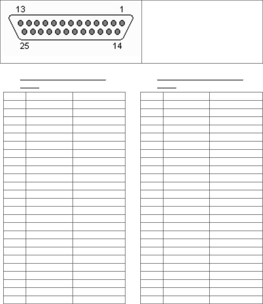
25.3.2
I/O Wiring—NetVision Plus
Cards
Pin Function Ext. Wire Colour
Pin 1 Alarm input 1 Black
Pin 2 Alarm input 3 White
Pin 3 Ground Red
Pin 4 Alarm output 2 Green
Pin 5 Not used Orange
Pin 6 Alarm input 5 Blue
Pin 7 Alarm input 7 Black/White
Pin 8 Ground Black/Red
Pin 9 Alarm input 10 Black/Green
Pin 10 Alarm input 12 Black/Orange
Pin 11 Alarm input 13 Black/Blue
Pin 12 Alarm input 15 White/Black
Pin 13 Ground White/Red
Pin 14 Alarm input 2 White/Green
Pin 15 Alarm input 4 White/Blue
Pin 16 Alarm output 1 Red/Black
Pin 17 Alarm output 3 Red/White
Pin 18 Ground Red/Orange
Pin 19 Alarm input 6 Red/Blue
Pin 20 Alarm input 8 Green/Red
Pin 21 Alarm input 9 Green/Orange
Pin 22 Alarm input 11 White/Red/Black
Pin 23 Ground Red/Black/White
Pin 24 Alarm input 14 Black/White/Red
Pin 25 Alarm input 16 Black/White/Green
25.3.3
I/O Wiring—NetVision Elite
Cards
Pin Function Ext. Wire Colour
Pin 1 Alarm input 1 Black
Pin 2 Alarm input 3 White
Pin 3 Alarm input 5 Red
Pin 4 Alarm input 7 Green
Pin 5 Alarm input 9 Orange
Pin 6 Alarm input 11 Blue
Pin 7 Alarm input 13 Black/White
Pin 8 Alarm input 15 Black/Red
Pin 9 Ground Black/Green
Pin 10 Ground Black/Orange
Pin 11 Alarm output 1 Black/Blue
Pin 12 Alarm output 3 White/Black
Pin 13 Not used White/Red
Pin 14 Alarm input 2 White/Green
Pin 15 Alarm input 4 White/Blue
Pin 16 Alarm input 6 Red/Black
Pin 17 Alarm input 8 Red/White
Pin 18 Alarm input 10 Red/Orange
Pin 19 Alarm input 12 Red/Blue
Pin 20 Alarm input 14 Green/Red
Pin 21 Alarm input 16 Green/Orange
Pin 22 Ground White/Red/Black
Pin 23 Ground Red/Black/White
Pin 24 Alarm output 2 Black/White/Red
Pin 25 Not used Black/White/Green
This is a 25-PIN connector that is NOT
close to the regular PC connectors
(monitor, network, etc.).
Output Specifications:
• Open collector output
• High impedance at normal
• Sink current at alarm