
User`s guide


Table Of Contents
- Copyrights and Trademarks
- Disclaimer
- Welcome to NetVision
- Common / Daily Tasks
- 5 Starting your Software and Logging In
- 6 Alarm / Reporting Features and 'Chatting'
- 7 Playing or Downloading Video Recordings
- 7.1 Overview--Types of Playback
- 7.2 Playback--Technical Details
- 7.3 Synchronized Playback (v2.3 SP2)
- 7.4 Video Search (v2.3 SP2)
- 7.5 Searching for Motion
- 7.6 Working with the Playback Screen
- 7.7 Viewing and Printing 'Snapshots'
- 7.8 Working with the File List
- 7.9 Quad Playback
- 7.10 Server Management--Identifying Remote Servers for Playback
- 8 Viewing Live Cameras
- 9 Recording Camera-Views
- System Administration and Maintenance
- 10 Tasks Applicable to Remote Stations and the Video Server
- 10.1 PC Date and Time
- 10.2 Checking your Software Version
- 10.3 Introduction to Video File Management (Filekeeping and Housekeeping)
- 10.4 To Allow Using a Blank CD (Roxio - Easy CD Creator 5 basic with DirectCD)
- 10.5 Filekeeping (v2.3 SP2)
- 10.6 Housekeeping
- 10.7 Automatic Video File Management (Self Housekeeping)
- 11 Tasks Performed at the Video Server Only
- 10 Tasks Applicable to Remote Stations and the Video Server
- System Configuration
- Software Installation and Network Set Up
- 19 PC Requirements
- 20 Software Installation or Upgrade
- 21 Network and Connectivity Issues
- 21.1 General Network Requirements
- 21.2 IP Addressing on the Network
- 21.3 Network Services
- 21.4 Network Ports
- 21.5 To Connect via the Internet
- 21.6 Remote User Permissions
- 21.7 For Remote Viewing, Recording, Playback, and/or Audio Monitoring
- 21.8 For Alarm Alerts
- 21.9 For E-Mail Alerts
- 21.10 Windows Dial-Up Networking Connection (i.e., not via the Internet)
- 21.11 Network Usage
- Reference Topics
- 22 Using the Small Remote Module
- 23 Remote Configuration
- 24 The WatchDog Feature
- 25 Hardware Reference
- 26 Troubleshooting
- 27 Using the ATM Interface Option
- 28 Working with the Older Playback Engines
- 28.1 The Video Playback Feature (Micro DVR)
- 28.2 Step 1: Open the Video Player
- 28.3 Step 2: Local / Remote, and Connection Screen
- 28.4 Step 3: Searching for Video/Alarm Files
- 28.5 Smart Motion Search (Micro DVR)
- 28.6 Step 4: Playing a Video
- 28.7 Window Options and File Properties (Micro DVR, Quad Player)
- 28.8 Viewing and Printing 'Snapshots' (Micro DVR)
- 29 Viewing Cameras through a Web Browser
- 30 Setting up an IP Camera or Video Server module (v2.3 SP2)
- 31 Panoramic Video Surveillance--PVS (v2.3 SP2)
21-0400E v2.3.3
Welcome Common Admin Config Install
Tech-Ref
115
25.3
Wiring Reference
25.3.1
About External Alarm Inputs
Each camera can have an external sensor
associated with it (dry contact). If enabled, the
camera-view will be recorded whenever the
sensor is tripped (and if set up, a ‘pre-
recording’ of just before the event will also be
available). This can be instead of, or in
addition to video motion sensing.
Tip: External inputs can also: • Trigger alarm-alerts
and email; • Aim an associated (PTZ) camera to a pre-
defined ‘preset’ position; • Display the camera image
on a TV monitor until acknowledged by someone (TV-
Out / Spot Monitoring). For details, check the index for
a desired keyword.
The sensors can be either normally open, or
normally closed (as long as you 'tell' the Video
Server software which type of sensor you are
using). This is done under:
[Utility]
ÖRecorder Setting ÖAlarm .
Related Topics:
18.3 External Sensors and Recording Duration
Three outputs are also included to provide
signalling functions. One output fires when
any external sensor is tripped, a second one
triggers when motion is detected in any
camera-view, and the third output is activated
when either of these conditions occurs.
The inputs and outputs are connected through
a DB connector on the back of the Video
Server.
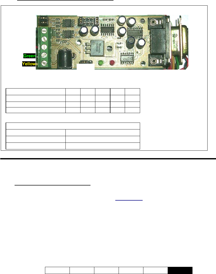
25.2.6
RS232 – RS422/485 Converter Detail
JP1 Reference 54321
Typical (default)
9
---
9
Half Duplex (Tx/Rx on same line)
9
-
9
-
9
Half Duplex w/RTS Control -
99
--
Other Jumpers
JP2
9
(always)
JP4
9
(always)
JP3
per PTZ voltage (see diagram)
Front of NetVision
server (capture station)
Ø
Blue
Black
Red
Green
Yellow
Serial IN
(RS232)
12V
Ù
5V
JP3
JP4
JP2
JP1
5 4 3 2 1