
User manual


Page 20 U S E R M A N U A L AUTOSAT 2 CONTROL
5. Before turning in the screws, please fill the holes with Sikaflex. Make a sealing joint
around edge of the base plate. Now carefully tighten all the screws.
6. For the three outgoing cables drill a hole (min. 15 mm diameter) through the roof.
7. To fix the cables to the roof, it is recommended to use a 20 x 20 mm cable duct. Wrap
the cable contacts with adhesive tape to avoid damage. Each of the 3 cables is
already fitted with a grey plastic PG-gland. Unscrew the 3 narrow plastic nuts and pull
them off the cables. Loosen the sealing caps on the other side of each gland. Carefully
push the 3 cables with the glands through the optional 20 x 20 mm cable duct and
then through the side into the cable feed through – push the 3 nuts back onto the
cables - screw the glands into the holes of the feed through. Now push the cables
through the roof. Fix the junction box with Sikaflex-252 and three 3.9 x 25 self tapping
screws. Position and fix the cables to the roof. If using a 20 x 20 mm cable duct, attach
it to the roof with Sikaflex-252, leaving enough room to reach the sealing caps of the
PG-glands. Finally tighten the sealing caps.
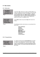
Figure: Cable gland feed through with cables and PG glands
.
8. The aerial dish can only be fitted after the system has been connected to the power
supply and is ready for operation, since the aerial arm has to be raised electrically
from the parking position. Switch the AutoSat 2 on - wait until the arm has been raised
sufficiently - then interrupt the power supply (remove cable). Fasten the dish with the
four nuts and the four washers supplied.
Flat aerial: Carefully tighten nut of aerial cable on aerial with an 11mm open ended
spanner but not too tightly.
This concludes work on the roof.