Page 2 USER MANUAL AUTOSAT 2 CONTROL
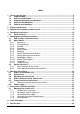
Index 1 Please read this first...................................................................................................... 5 1.1 Important Note:...................................................................................................... 5 1.2 Safety considerations ........................................................................................... 6 1.3 Important operating considerations..................................................................... 6 1.
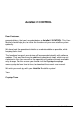
AutoSat 2 CONTROL Dear Customer, congratulations, that you have decided on a AutoSat 2 CONTROL. This User Manual should help you, to utilise the functions of your new satellite system optimally. We have kept the operational details as understandable as possible, while keeping them short. The functional range of your device will be expanded steadily with software updates.
1 Please read this first Before commencing the installation, check the consignment for completeness. The following items are contained in the shipment: 1 1 1 1 4 4 4 12 1 1 1 1 Control unit box External unit and satellite aerial (dish or flat aerial) Connecting cable for power supply, 0.
1.2 Safety considerations For your protection, read the safety considerations carefully before you start running your new equipment. The manufacturer accepts no liability for damages arising from faulty handling and failure to comply with safety provisions. If the equipment has been modified, Crystop is no longer responsible for ensuring, that the legal requirements (i.e. equipment and product safety laws, electromagnetic compatibility) are complied with.
1.4 Disposal considerations The packaging of your unit consists exclusively of reusable materials which should be recycled. Make sure, that empty batteries from the remote control unit are not disposed in the household rubbish, but are returned for disposal as hazardous waste to a dealer. 1.5 General considerations Always make sure (even when your AutoSat 2 will be retracted by your starter key) that the system has really retracted when starting your vehicle.
2 Figure Control Panel Figure Control-Box Page 8 USER MANUAL AUTOSAT 2 CONTROL
3 Sequence of automatic satellite search The AutoSat 2 Control satellite system is turned on with the “On / Off” button on the control unit. After turn on, the satellite to be searched for will be shown in the display (factory setting ASTRA1 or the last received). In the top right of the display 5 seconds are now counted down, during which time you may call up the main menu via the “Menu” button. If no button is pressed, the satellite search starts (LED next to the “On / Off” button goes out).
4 Operating instructions 4.1 Quick reference Function Description Switch on The satellite system is switched on with the ”On / Off“ button on the control unit or on the optional remote control unit. “On / Off“ button Retract antenna + Switch off If the control unit is switched off (display off) the “On / Off“ button is pressed twice - once to switch the control unit on and another time to “On / Off“ button retract the antenna and switch off.
5 Handling the operating instructions For the button names used in the following operating instructions you will find equivalent symbols in the Quick reference (page 10) which are used on the buttons of the control unit. e.g.: “On / Off“ button In the text buttons are shown bold and in italics. e.g.: “On / Off“ button The figures in the text are numbered (Fig. 1), to maintain a clear reference to the text. Your display may vary if a different satellite is selected. Menu texts are shown bold. e.g.
5.2 Menu details 5.2.1 Main menu Fig. 1 To reach the Main menu, the system must be turned on. On initial turn on, Fig. 1 will show in the display. The name of the selected satellite will be shown in the middle line. Now you have 5 seconds to press the “Menu“ button. If no button is pressed within this time, the system automatically returns to stand by mode or starts a satellite search, depending on whether the system has reception or not. If the “Menu“ button was pressed, Fig. 2 will show in the display.
5.2.3 Satellite The sub menu “Satellite“ (Fig. 4) allows the selection of the satellite to be searched. The list of available satellites is shown The list of available satellites is shown (Fig. 5). Using the “Plus“ or “Minus“ button you can select the required satellite. Confirm the selected satellite by pressing the “Enter“ button. Subsequently the system will enter search mode and point the antenna to the selected satellite.
ASTRA 3A * ASTRA 1 > HOTBIRD Fig. 7 FRQ: 11804 SR : 27500 POL: vert Fig. 8 By pressing the "Enter" button, you confirm your choice and will be directed to the submenu (Figure 8) where you can change parameters such as frequency, symbol rate, polarisation, orbit position and the skew angle. Programming an unlisted satellite is best achieved by selecting the "USERSAT" option. As in the main menu, the modifiable parameters appear in a list.
5.2.6 Backlight The sub menu “Backlight“ (Fig. 11) lets you change the background lighting of the LC display. You can select “OFF“, “ON“ or “AUTO” mode. The standard mode is “AUTO”. Fig. 11 Fig. 12 In the backlight mode “ON“ the display is illuminated, as long as the control unit is switched on. In the backlight mode “OFF“ the backlight is permanently switched off. In “AUTO” mode the illumination of the display switches off after approx. 60 sec, but turns on again if any key is pressed.
5.2.8 Manual Azimuth of the Antenna The sub menu “Man. Azi.“ (Fig. 16) lets you turn the antenna manually clockwise or anti-clockwise. This function is necessary for installation and service work and has no further bearing on the operation of the system. Fig. 15 The current position of the antenna is shown in the second row. The third row displays the current signal reception strength. Manual Azi. Pos: 63,20 CN: 156 Fig. 16 5.2.
5.2.11 Language The sub menu “Language“ (Fig. 19) (“Sprache” in german) lets you select the language for all menus. Currently available languages are: Deutsch, English, Francais, Italiano and Nederlands. Fig. 19 5.2.12 Factory settings Man. Azi. Language > Factory set. Upon execution of the menu item "Factory settings" (Figure 20), all satellite parameters and modifiable settings will be reset to the original delivery conditions.
6 Mounting instructions !!! Note: Please read the mounting instructions before starting the installation 6.1 Choice of installation site Initially choose sites for positioning the control unit and your receiver. Unless the control unit has a remote control option, it should be mounted, so that its display can be read and the buttons can be operated. The receiver should be as close to your TV set as possible and be seen from where you sit, since the receiver is controlled by an IR remote control.
Now select a suitable free space on your roof. The direct vicinity of the site selected must be free from objects higher than 20 cm, which might shadow the aerial. When this installation site has been found, once again make sure that the control unit is within a cable length of 4 m. If not, relocate the installation site or the control unit or extend the cable by an additional extension set (obtainable from us). Please do not extend the cable without consulting us first. 6.
5. Before turning in the screws, please fill the holes with Sikaflex. Make a sealing joint around edge of the base plate. Now carefully tighten all the screws. 6. For the three outgoing cables drill a hole (min. 15 mm diameter) through the roof. 7. To fix the cables to the roof, it is recommended to use a 20 x 20 mm cable duct. Wrap the cable contacts with adhesive tape to avoid damage. Each of the 3 cables is already fitted with a grey plastic PG-gland.
6.4 Cable connection to the Control unit 6.5 Figure Control unit connectors Lay cables from the external unit on the inside of the vehicle to the control unit. The cables should not rub on sharp edges and should not be laid close to sources of heat. Prior to inserting contacts in the connector housing, ensure that the contacts are in a faultless condition and are not bent. In particular, contact blades must not have excessive spacing.
6.5.1 Sketch of connector housing (rear view!!) 6-core cable: 3- core cable: 6.6 Power supply Run the AutoSat 2 Control only on 12 V batteries or a battery charger or power pack supplying a continuous current of 10 Amps DC. Warning: For 24 Volt vehicle mains, a 24 V to 12 V converter will be required. A 4 pole connector with a short cable is provided. Connect the 4 wires to the vehicle power supply with suitable connectors. To keep cable losses to a minimum.
7 Connection and initial operation 7.1 Mounting the control unit To fix the control unit or the receiver, it is best to use double-sided adhesive tape Scotch 3M or Tesa Power Strip. If screws are used, always make sure they do not make contact with the electronic circuit or cause any other damage. 7.1.1 Satellite aerial connector The satellite aerial cable is terminated with an F-Connector on delivery. Check the connector for damage and good seating before mounting. The centre conductor must not be bent.
7.1.2 Connection external motor unit Prior to plugging in the connector to the external motor unit, check it again for correct seating of the contacts. If all contacts are fully inserted and in the correct positions (see page 21) the connector may be plugged in. 7.1.3 Connection power supply Prior to connecting the control unit with the vehicle power supply, check the supply connector again, to avoid possible damage due to incorrect connections. 7.1.
8 Fault elimination Fault Remedy 1) Check, that there is a free line of sight to the Satellite. Trees will block reception! 2) Make sure, that the required Satellite can be received with your size aerial at your current location. 3) At the fringe of the Satellite footprint, change the Search mode from “Course” to “Fine” and repeat the search. 4) The Satellite search parameters have changed. Check with us, whether there are new parameters or order a current Flash card.
9 Specification Power supply: Supply voltage (max. ratings) Voltage on control line D+ 10...15V DC 10...30V DC Current / Power input Search mode typ. Reception mode typ. GPS (optional) Current limit, motors 3 A / 36 W 0,01 A / 0,03 W 0.25 A / 3 W approx. 8 A LNB: LOF Noise level low / high band LNB-control single LNB twin LNB 9.75 / 10.6 MHz 0.3 dB 0.4 dB 14/18 V, max.
AUTOSAT 2 CONTROL USER MANUAL PAGE 27
Gesellschaft für Anzeigesysteme mbH Durlacher Allee 47 76131 Karlsruhe : +49 (0)721 / 61 10 71 : +49 (0)721 / 62 27 57 info@crystop.de www.crystop.