
Operating instructions


AUTOSAT 2 OPERATING INSTRUCTIONS PAGE 7
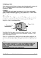
4.0 Cable Connection to AutoSat2 Receiver
4.1 External Unit
Lay cables from external unit to receiver. Cables may not rub against sharp
edges or be laid close to heat sources. Ensure prior to engaging contacts in
connector housing that contacts are in faultless condition and not bent. In
particular, contact blades must not have excessive spacings. Engage
contacts in connector housing to the following sketch. Individual cable cores are
marked in colours and connector-housing recesses are numbered to eliminate
confusion.
Work very carefully, because contacts, once inserted, cannot be removed.
Ensure that contacts are fully inserted to allow blade to engage (can be heard
as a click). After inserting all contacts, push connector housing together in
vertical direction to contacts.
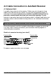
Sketch of connector housing (rear view!!)
6-core cable: 3-core cable:
1 2 3 4 5 6
7 8 9 10 11 12
brown (thin)
pink
green
yellow
grey
brown (thick)
blue
black
white
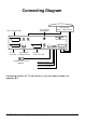
For power supply connection see next page