Intelligent Satellite Receiver System for Motor Homes and Caravans Operating Instructions GB
Important Notes: Please read these operating instructions before installation and start-up of your AutoSat2. Always make sure (even when your AutoSat2 will be retracted by your starter key, see chapter 4.2 Power Supply) that the system has really retracted when starting your vehicle. In case of interrupted supply voltage, for instance, the aerial can no longer be automatically retracted.
Contents I. ASSEMBLY INSTRUCTIONS ........................................................................ 4 1.0 Scope of Supply........................................................................................ 4 2.0 Selection of Installation Site ...................................................................... 4 2.1 Receiver................................................................................................. 4 2.2 External Unit .......................................................
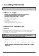
I. Assembly Instructions !!! Note Please read these assembly instructions before commencing installation! 1.0 Scope of Supply 1 Receiver with integrated motor control and IR remote control 1 External unit and satellite aerial (dish or flat aerial) 1 Connecting cable for power supply, 1 m length 1 12-way connector housing 1 Assembly material for satellite aerial self-tapping screws 3.9x25 1 Junction box 1 Support block for dish aerial or sealing cap (Waterlock) for plug of flat aerial 2.
2.2 External Unit When selecting the installation site, please notice that cables to the external unit are 4 (6) m long and ensure that the external unit will have a sufficient clearance for rotation. Flat aerial: The AutoSat2 (50 cm flat aerial) has a base of 41.5 x 41.5 cm and in search mode will require a maximum radius of 25 cm for objects of up to 15 cm height. For higher objects, a radius of 45 cm will have to be reserved. Dish aerial The AutoSat2S (85 cm dish) has a base of 41.5 x 41.
3.0 Mounting the External Unit Proceed in the following sequence Use Sikaflex-252 as an adhesive/sealant 1. Position external unit with the outgoing cable pointing towards the rear of the vehicle. 2. Drill 2 diagonal holes from the base plate of the external unit by using a 2.4 mm drill. 3. Fix external unit by two self-tapping screws of 3.9 x 25 to the roof. Lightly tighten screws. The aluminium coating of the roof is thin and the screws may be easily tightened too hard. Then drill remaining holes.
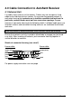
4.0 Cable Connection to AutoSat2 Receiver 4.1 External Unit Lay cables from external unit to receiver. Cables may not rub against sharp edges or be laid close to heat sources. Ensure prior to engaging contacts in connector housing that contacts are in faultless condition and not bent. In particular, contact blades must not have excessive spacings. Engage contacts in connector housing to the following sketch.
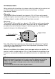
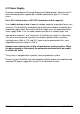
4.2 Power Supply Proceed in accordance with wiring diagram on following page. Connect short 3core connecting cable supplied by a suitable connector to your 12 V vehicle mains. For a 24 V vehicle mains, a 24V/12V transformer will be required. Use a cable section of min. 4 mm2 for voltage supply to keep cable losses to a minimum. The AutoSat2 should ideally be directly connected to the battery by a dedicated supply cable. Ensure that no other major users are connected to the same supply cable.
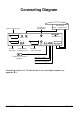
Connecting Diagram External unit TV connection HF modulator VCR scart connection Aerial Motor control CRYSTOP RS232 Made in Germany TV LNB VCR R TV TV scart connection L Audio Decoder Audio outputs Left/right channel Control incl. IR receiver (optional) Aerial Input IR Sensor + 12V - D+ External Unit Decoder Scart connection RED: 12V (4 mm²) BLACK: mass (4 mm²) Blue: D+ or terminal 15 Connecting facilities for TV with/without a scart and video recorder see appendix A.1.
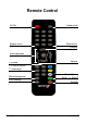
Remote Control On/Off Audio on/off Display menu Exit menu Channel list Channel selection Menu operation Volume TV/Radio TV: Exit all menus 1st channel of actual satellite Mono / Stereo Astra1 <-> Astra2* Menu background Save settings PAGE 10 Standby OPERATING INSTRUCTIONS AUTOSAT 2
II. Operating Instructions 5.0 General AutoSat2 DVB offers digital channels of factory preset or personally programmed satellites of the satellites ASTRA 1, HOTBIRD and ASTRA 2. 5.1 Enabling Please enable your TV first to enable On Screen Display of your AutoSat. AutoSat2 On: Use centre key at front of unit or key at separate controller (optional) only. AutoSat2 Off: Use centre key at front of unit or key at separate controller (optional) or ON/OFF key on remote control.
5.3 How To Select a TV or Radio Channel Channel selection is effected by the following keys: - , keys -0…9 - LIST - TV, RADIO Press briefly: 1 change of channel Press and hold: fast channel changes Channel direct input, 1, 2 or 3-digit. For input of multi-digit numbers enter figures fast. Station list, see chapter 7.1 Switch TV <-> Radio 5.4 Volume Control Set volume by and keys.
6.0 Explanation of Menus 6.1 MAIN MENU After pressing the MENU key, the main menu will be displayed. MAIN MENU , AUTOSAT: Search satellite Fine tuning Standby: OFF Manual see chapter 6.2 see chapter 6.3 see chapter 6.4 see chapter 6.5 RECEIVER Channel setting Sound Installation see chapter 6.6 see chapter 6.7 see chapter 6.8 key: Select desired sub-menu or function. The submenu or function will be marked by the arrow. Activate sub-menu or function Exit main menu or sub-menu OK key: MENU key: 6.
!!! Note: Should the same search cycle be activated for the satellite found (ASTRA found -> Search ASTRA) AutoSat2 will no longer find this satellite during this search cycle, due to the first found position having been blocked by the new search cycle -> Switch AutoSat2 off and on again. 6.3 FINE TUNING Key sequence: MENU OK Display of main menu, arrow on FINE TUNING Activate fine tuning Re-optimisation of receiving position. This may be required should reception be affected by external influences.
6.5 MANUAL MENU Key sequence: MENU 2x OK Display main menu Arrow on MANUAL Display of MANUAL menu AUTOSAT manual Aerial : Key : : : POS: ELE: AZI: C/N / AGC Press key briefly Press + hold key C/N / AGC: POS ELE/AZI: Key C: …degrees …degrees Movement in small increments Continuous movement Display of C/N and tuner AGC value (DVB mode only). Aerial position in horizontal and/or vertical alignment. Switches between coloured background and image 6.
Station search: Add new stations Satellite: For setting the satellite on which a station search is to be effected (the satellite must have been preset in the above menu item. The aerial must be tuned to the satellite). Set transponder manually: Search for any stations on this set transponder, for accurate selection of which stations will be saved during a search (for instance English language only).
6.8 INSTALLATION MENU Key sequence: MENU 5x OK Display of main menu Arrow points at INSTALLATION -> Display of INSTALLATION menu: INSTALLATION , key: , key: STORE key: MENU key: Language: Preset: English STORE LNB frequency: 9.75 / 10.6 Select line Change setting Store settings Exit menu 6.8.1 Select Language For selection of four languages: German English STORE key: French Dutch For permanent storage of language selected.
7.0 Special Functions 7.1 LIST Key: Station List After pressing the LIST key, a list of stations saved will be displayed. The present station is marked by an arrow / highlighted.
7.2 STANDBY Key Switch AutoSat2 to Standby mode by pressing the STANDBY key. The aerial will remain in receive position and the receiver will switch off (display: OFF). There is no power consumption in this condition. However, the AutoSat2 may not be switched on by remote control but only at front of unit. To remind you that the aerial is extended, an LED will flash on the front of the unit and the separate controller (optional). Power consumption of this LED is negligible (0.1 W).
A. Appendix A.1 Connecting Facilities Connection of AutoSat2 receiver to a TV set Setting at TV set: VCR TV R L TV AutoSat2 Audio For connection by SCART-cable: Switch TV to AV or channel 0 Scart-cable or HF-cable For connection by HF-cable: Tune TV set to preset AutoSat channel (see specification: TV connection HF-modulator). The channel may be adjusted by using the # key: see chapter 7.6.
Connection of AutoSat2 receiver to a TV set and a video recorder Setting at TV set: VCR TV R L TV For connection by SCART-cable: AutoSat2 Audio Switch TV set to AV or channel 0 Scart-cable In this configuration the VCR may record from AutoSat by Scart-cable. Playback is possible via Scart by switching AutoSat channel 0 or via HF-cable without AutoSat being activated.
A.
A.3 Faults and Remedies Fault Remedies No satellite found 1) Check whether sight is free in southerly direction. There will be no reception under trees! 2) There is no transmission on your selected station, try another station for search. 3) Whilst moving about in marginal European areas: for searching switch to a station, which can be positively found. 4) Check aerial cable to external unit (firm attachment of connector, cable break) 1) Check connection to TV set.
A.4 Specification Power supply Supply voltage Supply voltage control line D+ Current / power input Search mode typ. Reception mode typ. Standby mode typ. Current limit, motors LNB control 10…16 V DC 10…30 V DC Approx. 3 A / 36 W 1.2 A / 15 W 0.8 A / 10 W approx. 8 A 14/18 V, 300 mA max. 22 kHz, Toneburst LNB LOF Noise level low / high band single LNB twin LNB 9.75 / 10.6 MHz 0.9 / 1.1 dB typ. 1.0 / 1.2 dB typ.
CINCH connections AUDIO L/R AUTOSAT 2 Audio left / right see SCART TV connection OPERATING INSTRUCTIONS PAGE 25
CRYST P O Gesellsc h a f t f ü r A n z ei g esy st em e m b H Durlacher Allee 47 76 131 Karlsruhe : 0721 / 61 10 71 : 0721 / 62 27 57 www.crystop.