
User's Manual


CRXi
µ
µµ
µ
Core Module
CR
µ
µµ
µ
X Logic,
2001 all rights reserved
8
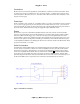
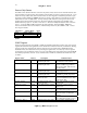
This diagram (Figure 1) completes the requirement for a ‘NULL’ connection and would require a straight
non-null serial cable. If the connection was wired RXD to RXD and TXD to TXD, use of a NULL serial
cable would be required. No special software is needed – communication is established through a standard
terminal emulator. The default settings are 19200 bps, 8, N, 1. Consult Crux Logic for baud rates other than
this default.
NVSRAM Memory
The CRXi is furnished with a 32K byte non-volatile SRAM (U3). No battery is required – data can be
retained in RAM practically indefinitely. Simtek claims 100 year data retention. This makes the CRXi ideal
for data logging and applications where configuration data must remain intact yet be changeable. The
Simtek STK15C88 is a fast SRAM with a nonvolatile EEPROM element incorporated in each memory cell.
Data transfer from the non-volatile EEPROM to the SRAM occur automatically on powerup and transfer of
the SRAM to the EEPROM occur automatically on powerdown. This action is completely transparent to
the user and will appear as a battery backed SRAM would. In addition to the automatic store and recall
operation, there are software initiated store (see Table 3) and recall operations. Using the software store
cycle can insure data is copied to the EEPROM element before powerdown.
Autostore on powerdown is limited to the following conditions. The STK15C88 uses system capacitance to
perform an automatic store on powerdown. As long as the system power supply takes at least 10 mS to
decay from 4.5 VDC to 3.6 VDC, the SRAM will safely and automatically store the SRAM data into
EEPROM on powerdown. These conditions are usually easily met with a good power supply. If user cannot
guarantee this decay ramp, the software store operation can be used.
The software store is initiated by executing sequential reads from six specific address locations. These must
be read in sequence and cannot be interrupted by any other read or write sequence, or the autostore will be
aborted.
Read address 0E38h
Read address 31C7h
Read address 03E0h
Read address 3C1Fh
Read address 303Fh
Read address 0FC0h
Table 3
The last entry, read of address 0FC0h initiates the store operation. To perform a recall operation, the same
sequence of addresses are read with the exception of the last entry. The sixth read should be to address
0C63h. For detailed information on the Simtek NVSRAM, refer to SIMTEK
4
data book.
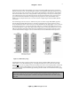
The NVSRAM is mapped to the 32767 (7FFFh) contiguous data bytes in the 80C320 data space beginning
at address 0000h (see Figure 2).
Additional Scratchpad RAM
In certain CRXi modules, an additional 2048 (800h) bytes of SRAM is available. This memory is volatile
and resides on the PSD flash (U2). Its location in the memory map is immediately following the NVSRAM
and is mapped from 8000h to 87FFh (see Figure 2). In CRXi models without scatchpad RAM, the address
space 8000h to 87FFh is not mapped. Reading or writing to this area will produce unwanted results and
should be avoided.
Flash ROM
The heart of the CRXi module is the PDS/Flash part. PSD is an acronym for ‘Programmable System
Device’ and contains 2 flash memory regions and a simple PLD (programmable logic device) that handles
all the glue logic such as memory latches and chip selects. This is what gives the CRXi its versatility with
such a low chip count.