
User's Manual


CRXi
µ
µµ
µ
Core Module
CR
µ
µµ
µ
X Logic,
2001 all rights reserved
7
Connections
Because the end users hardware applications are all different, no headers are soldered to the board. These
are inexpensive and easy to install. This is not a cost saving measure – we believe this provides for more
connection options. All header pins are on .100 centers with a .040 hole diameter. This will satisfy a wide
range of connector types.
Power Input
Power is supplied to pins on header J1. A regulated 5 VDC, ±.125 volts is recommended. Apply +5 VDC at
pin 1 or pin 37. Apply ground to pin 20 or pin 56. It does not matter which pin is used – pins 1 and 37 are
connected internally as well as pins 20 and 56. Power supply must be capable of delivering a minimum of
80 mA of current. Additional circuitry using this supply will require additional current.
Resets
Reset circuitry is present on the CRXi to facilitate hardware resets. This consists of a microcontroller
supervisor, U4, that holds the microcontroller and PSD in a reset until voltage reaches a stable operating
level and a 74HC14 schmitt trigger, U5, to clean up reset edges and invert signals (PSD is low reset,
microcontroller is a high reset). Additional circuitry can be added by the user if needed. Pin 19 on J1 is an
active low reset input. For development a normally open momentary switch could be added between pins
19 and 20(GND) to facilitate resets. Holding this line low for a minimum 150 uS resets all hardware. Reset
trip point is 4.625 VDC, ± .125 VDC.
Serial Port Interface
Communication with the CRXi module is accomplished through the microcontrollers serial port 0, pin 11
(receive) and pin 12 (transmit) on header J1. In order to establish connection with a PC, an RS-232 line
driver/receiver is necessary. This hardware is not present on the CRXi and is needed to change voltage
levels to be compatible with the CRXi. There are numerous IC’s available
3
– consult the data sheet of the
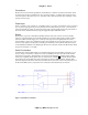
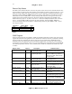
chosen device for wiring details and pinout. Connections are shown in Figure 1 below. Note the TXD
(transmit) output from the micro connected (via the RS-232 driver/receiver) to the receive (DB-9 pin 2) of
the PC and the RXD (receive) input to the micro connected to transmit (DB-9 pin 3) of the PC.
Figure 1 (Serial Port Connection)