
User's Manual

CRXi
µ
µµ
µ
Core Module
CR
µ
µµ
µ
X Logic,
2001 all rights reserved
15
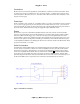
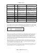
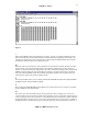
Figure 6
I
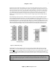
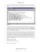
Dump internal RAM contents. No parameters are necessary. A single ‘I’ command will dump the entire
80h (128 decimal) bytes of internal 8051 RAM. To maintain backward compatibility with the 8051, only
128 bytes are dumped. Note, however, that the 8032, which includes the Dallas 80C320 microcontroller,
has 256 bytes of internal memory for general purpose use.
W
Write byte value to external memory. Three parameters are used with this command. The first is the value
to fill to memory, the second the starting address and the third the ending address. To write to just one
location, use the same starting and ending address. The write command can actually write to the entire 64K
(FFFFh) of external data space. Note that not all areas of memory are mapped and writing to undefined
areas will yield unpredictable results. Also the PLD configuration registers reside in upper memory and
writing to these registers may produce unwanted results.
Z
Zero all external data memory. This command will clear all NVSRAM and additional scratchpad RAM (if
applicable) between addresses 0000h and 8800h.
C
Run checksum of NVSRAM 0000h through 7FFFh. This command can be used to verify the non-volatile
storage capabilities of the CRXi module.
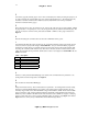
M
Run memory test. This test actually consists of four separate tests. First a “walking ones” test is run to
verify the data bus. Upon success this test will return 0, if failure a non-zero value. Next an address bus test
is run, covering all “power of two” addresses. A successful address bus test will return 0, failure will return
the offending address. The third test is a device test. This tests that the every bit in the device is capable of
holding both 0 and 1, and takes a bit longer to run than the other tests. This test will return 0 on success, or