
User's Manual
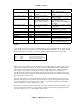

CRXi
µ
µµ
µ
Core Module
CR
µ
µµ
µ
X Logic,
2001 all rights reserved
12
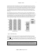
This is a brief summary of the configuration registers that reside in the CSIOP data space, and how to use
the basic I/O functions of the PSD (Flash) part. For more detail, refer to the ST Microelectronics data sheet
on the PSD913F2.
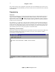
Programming
Overview
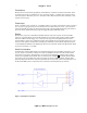
Programming the CRXi part is performed through the boards serial port 0. Minimal isolation hardware is
required, as outlined in Figure 1. A standard terminal emulator is all that is needed, such as Microsoft
HyperTerminal or Tera Term Pro
6
. The default serial port settings are 19200 baud, no parity, 8 data bits, 1
stop bit. User will need an assembler or compiler capable of generating Intel hex format files, targeted for
the 8051 series of microcontrollers.
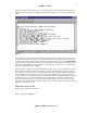
The commands ‘E’ ‘A’ (erase) and ’L’ (load .hex file) are mandatory commands needed for loading user
programs in the CRXi module. Other commands may or may not be needed – some were used during the
development of the CRXi module, and they remain in the bootloader code. Checksum and memory dump
can be used to verify NVSRAM is backing up data, write commands can be used to test peripherals, and
other commands can be used to verify proper operation of the CRXi module.
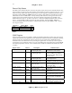
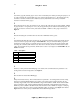
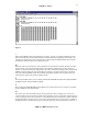
Establishing Communication
When proper connections are made between PC and the CRXi, the terminal is started and the CRXi can be
powered up. Immediately after powering up the CRXi, press any key on PC keyboard to establish
communications. Terminal should show:
Figure 4