CRUSADER CARAVANS OPERATING INSTRUCTIONS
Thank you for choosing a Crusader caravan. Welcome to the Crusader family. We wish you safe, enjoyable and trouble free caravanning. To assist you with familiarizing yourself with your caravan and its’ components we have prepared this basic handbook for your easy reference. We trust it is of benefit to you Basic Cleaning Just like your car, your caravan requires regular inspection, maintenance and cleaning. Clean the outside to remove any dirt and apply a suitable polish to protect it from the elements.
Chassis frame Should be checked regularly for rust and stress fractures, particularly outriggers and all cross member fixing points, ‘A’ frame, springs and spring hangers and stabiliser legs. Check for signs of movement around spring hangers, shackle plates and bushes, U-bolts and fish plates. Check corner stabilisers for ease of movement and ensure handle is in good condition. Check pull out step for cracks, rust and ease of operation.
Running Operation Connect the caravan tow plug to your vehicle and ensure all the caravan’s lights, indicators and brake lights work correctly. This procedure should be done prior to each departure Repairs Any suspected fault or damage to your caravan must be reported and attended to without delay by an authorised Crusader Caravans repair agent for warranty to be valid.
1
2
3
4
5
6
7
WARNING DO NOT OPERATE 240 VOLT SWITCH AND GAS SWITCH TOGETHER 8
9
10
11
12
13
14
15
16
17
18
19
20
21
22
23
24
25
26
Disclaimer: Please note: Every effort has been put into ensuring the accuracy of this booklet however Crusader Caravans do not take responsibility for any discrepancy that may exist.
CRUSADERCARAVANS.COM.AU Thirvale Pty Ltd in Trustees for The Seranth Trust trading as Dreamhaven Caravans – ABN: 20 799 107 499 8 Dreamhaven Court, Epping, VIC 3076 – Po Box 1105, Epping DC, VIC 3076 T: 03 9408 0166 F: 03 9401 5225 E: admin@crusadercaravans.com.
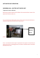
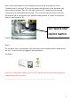
WATER PUMP OPERATION: The water pump is operated by an isolation switch located inside the van (as seen below) IMPORTANT. When connected to mains water pressure, ensure that this isolation switch is turned off – OTHERWISE you will continue to pump water from your water tanks and NOT mains water. ! ! ! The water pump is normally located under the fridge or in a separate cupboard nearby. See picture below.
! ! The water tanks are controlled by two separate isolation valves. It is ideal to close off one of these valves to ensure that water is only pumped from one tank at a time. This will prevent the pump drawing air from an empty tank if both valves are open. Then once this tank has emptied shut off and open the other valve to the water tank with water. This will then enable water to be pumped from the second tank without experiencing any difficulty or damage to the pump.
to fill the tanks. Once completed, you will notice two clear pipes also underneath the caravan. These clear pipes are your overflow indicators. You can now switch the valves off and continue to use main pressure once the tanks are full. Ensure that these valves are switched off when operating the water pump otherwise the pump may draw air into the system. ! ! ! ! ! Main Pressure Connection Switch valves IMPORTANT.
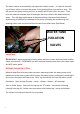
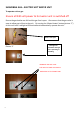
HOT WATER OPERATION: ! SUBURBAN HOT WATER UNIT ! Before you proceed to operate the Hot Water Unit ensure that there is water in the water tank of the hot water unit. You can check this by releasing the pressure release valve to ascertain that there is continuous water flow out from the unit. See picture 1.
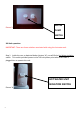
! ! 240 Volt operation: IMPORTANT: There are three 240volt switches associated in using the hot water unit. ! Step 1. Inside the van, as pictured below (picture ‘A’) you will find a Hot Water isolation switch. This switch is used to turn on the 240 volt power point where the HWU is plugged into to operate the unit. Picture ‘A’! ! Step 2. This ‘On / Off’ switch (picture ‘B’) is located on the unit and accessed from the external hatch opening.
! Step 3. The hot water unit is connected to a 240 volt power (on/off) wall switch located inside a cupboard near the unit. Ensure that this is plugged in and switched on. See below: ! ! ! ! If either one of these three switches is in the ‘OFF’ position then the hot water unit will not operate under 240 volt power.
Valve is now open ! Red light will alight when gas unit is operating or reheating Picture ‘C’ ! WARNING: DO NOT HAVE THE 240 VOLT AND GAS SWITCH OPERATING AT THE SAME TIME. ! ! TRUMA HOT WATER UNIT Before you proceed to operate the Hot Water Unit ensure that there is water in the water tank of the hot water unit. Also ensure that the cover is removed before turning the hot water unit on.
COVER TO VENT ! ! ! ! ! ! Remove cover before turning hot water unit on… otherwise unit will not operate ! !8
240 volt isolation switch to wall power point plug inside cupboard for hot water unit Gas switch ! ! ! ! ! ! ! ! ! ! ! ! ! ! ! WARNING DO NOT OPERATE 240 VOLT SWITCH AND GAS SWITCH TOGETHER !9
TRUMA GAS HEATER. ! Gas exhaust vent with cover on ! ! Gas cover MUST be removed before you start heater….otherwise UNIT will not operate ! Heating outlet vent and return air vent ! Grey outer switch operates gas heater or fan only.
MAINS POWER SWITCH The Mains switch allows 12 volt power to the caravan via the caravan battery Picture ! THE MAINS 12VOLT SWITCH IS NORMALLY LOCATED JUST INSIDE THE DOOR ENTRANCE ABOVE HEAD HEIGHT. ! ! ! 12 Volt power is drawn from the battery via the ‘Battery Protector’ switch which is located in the front boot of the caravan. (in most caravans).....
ON / OFF SWITCH TO BATTERY PROTECTOR ! The ‘CUT OUT VOLTAGE’ switch is located under the ON/Off switch on the ‘Battery Protector’ this should be left on 11.0 Volts to ensure that the battery does not exceed the voltage output. ! IMPORTANT: If the caravan is being used for lengthy periods under ‘House Power’ only.
battery losing charge. This will be noticeable when lighting inside the van fails to operate sufficiently or 12 volt power is no longer available. If this occurs YOU MAY lower the voltage output switch to 10.5 or 10 volts to reduce power. But always ensure that you return this switch back to 11.0 volts when battery is fully charged. ! ! ! This battery protector is governed by a 50amp fuse. The amber lights needs to be ‘on’ to ensure there is a 12 volt supply to the caravan.
! Battery Charger When the charger is operating correctly the ‘On Charge’ light will activate. If this fails then check that the lead is correctly plugged in to the power point and the back of the unit. The battery charger also has an ‘on/off’ switch on the unit this should remain ‘ON’ at all times. A fuse is located at the rear of the unit which needs to be unscrewed from the unit. What will accompany the “On Charge Light” will be one of the three other lights.....”Bulk”....Absorption”......”Float”.....
! TOILET CASSETTE Read manual for individual toilet system operation. ! Before operating any toilet system please ensure that the drainage cap is fitted to the external cassette unit. Dometic Toilet system ! Cap Thetford toilet system ! ! Release Latch To remove the cassette simply lift the green or yellow release latches (depending on the model) and pull out.
! GAS APPLICANCE SHUT OFF VALVE: Every gas appliances in the caravan has a safety gas shut off valve (also known as a ‘gas cock’). This valve enables for the gas to be shut off to the appliance (Cook top – Oven – Hot water unit – Fridge) during maintenance, repairs or cleaning.
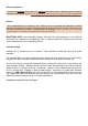
Manual changeover valve ! ! BRAKE SAFE SYSTEM: ! The brake safe device is designed to automatically apply the electric brakes to the caravan in the event of an accidental separation from the towing vehicle. ! Breakaway switch Cable to be affixed to the towing vehicle ! The metal cable is attached to a permanent anchor point on the towing vehicle with minimal amount of slack in the cable to allow the pin in the brake safe switch to be pulled out of its housing to activate the emergency braking system.
The brake safe system is powered by the battery which is housed in a container located in the front boot (All models except Tourline model) The battery is charged from the car via the number 2 pin on the trailer plug. By pressing the ‘press’ button you can check the power level of the battery (either Normal charge or Low charge will be displayed) Normal light indicates battery charged Low light indicator.
! Refer to wiring options sheet.....................car to caravan ! ! ! ! Shower head storage Travellers are advised to ensure that the shower head is stored by placing it in a wrapped clothe and placed on the shower floor. The shower head is not designed to remain in the cradle whilst travelling, because it likely to dislodge and thus damage.
Do not leave shower head in cradle ! ! Entrance door ! Customers are advised NOT to cover or restrict air flow to the door vent. This vent is designed as a safety measurement under the Standard Manufacturing Regulations.
DO NOT COVER OR RESTRICT AIR FLOW TO THIS VENT ! ! ! ! ! ! ! Fridge Fan Operation (On Selected Caravan Models) !21
! Fridge Fan fitted to the rear of the fridge. Thermostatically Controlled. I.E. when the fridge gets too hot the fan activates to create an air flow to cool the fridge coils. Fridge Fan isolation switch. Giving you the option to switch the fan off when in storage or during the night.
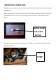
! ! ! ! ! ! WINEGARD ANTENNA: Raising the antenna to operating position turn the elevating crank (clockwise) in ‘UP’ direction about 13 turns or until resistance is reached.
Make sure antenna is in “UP” position. Pull down on the rotating plate to disengage ceiling plate and rotate. By Rotating this plate you are now rotating the antenna. ! Lowering antenna to travel position, Rotate antenna until pointer on directional handle aligns with the pointer on the ceiling plate. Turn level crank (counter clockwise) in “DOWN” direction about 13 turns or until resistance is noted. Antenna is now locked in travel position.
Black button: DVD Connection Port (Yellow RCA lead to connect to yellow port on TV Digital booster for Winegard Antenna.
! !26