
Technical information


Macro-Tech 600/1200/2400 Power Amplifiers
Page 24
The two channels may be used together to double the
voltage (Bridge-Mono) or the current (Parallel-Mono)
presented to the load. This feature gives you flexibility
to maximize the power available to the load.
A wide bandwidth, multiloop design is used for state-
of-the-art compensation. This produces ideal behavior
and results in ultra-low distortion values.
Aluminum extrusions have been widely used for heat
sinks in power amplifiers due to their low cost and rea-
sonable performance. However, measured on a watts
per pound or watts per volume basis, the extrusion
technology doesn’t perform nearly as well as the heat
sink technology developed for
Macro-Tech
amplifiers.
Our heat sinks are fabricated from custom convoluted
fin stock that provides an extremely high ratio of area
to volume, or area to weight. All power devices are
mounted directly to massive heat spreaders that are
electrically at the Vcc potential. Electrifying the heat
spreaders improves thermal performance by eliminat-
ing the insulating interface underneath the power de-
vices. The chassis itself is even used as part of the
thermal circuit to maximize utilization of the available
cooling resources.
5.2 Circuit Theory
Each channel is powered by its own power transformer
T100 or T200. Both channels share a common low-
voltage transformer TF-1. The secondary output of
T100 is full-wave rectified by D109 and is filtered by a
large computer grade capacitor. D104 through D107
provide boosted voltage to power LVAs and predrivers.
A thermal switch embedded in each transformer pro-
tects it from overheating.
The low-voltage transformer TF-1 uses a separate
winding on the fan motor. The TF-1 output is rectified
by diodes D1, D2, D3 and D4 to generate an unregu-
lated 24 volts. Monolithic regulators U1 and U2 provide
a regulated ±15 volts.
5.2.1 Stereo Operation
For simplicity, the discussion of Stereo operation will
refer to one channel only. Mono operation will be dis-
cussed later.
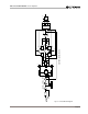
Please refer to the block diagram in Figure 5.1 and the
schematics provided at the back of this manual.
The input signal at the phone jack passes directly into
the balanced gain stage (U104-C and U104-D). When
the
P.I.P.
module is used, the input signal first passes
through the
P.I.P.’s
circuitry and then to the balanced
gain stage.
5 Technical Information
5.1 Overview
Your
Macro-Tech
amplifier incorporates several new
technological advancements including real-time com-
puter simulation of output transistor stress, low-stress
output stages, an advanced heat sink embodiment
and the Programmable Input Processor (
P.I.P.
) expan-
sion system.
Custom circuitry is incorporated to limit temperature
and current to safe levels making it highly reliable and
tolerant of faults. Unlike many lesser amplifiers, it can
operate at its voltage and current limits without self-
destructing.
Real-time computer simulation is used to create an
analogue of the junction temperature of the output tran-
sistors (hereafter referred to as “output devices”). Cur-
rent is limited only when the device temperature
becomes excessive (and by the minimum amount re-
quired). This patented approach is called Output De-
vice Emulation Protection (or
ODEP
). It maximizes the
available output power and protects against overheat-
ing—the major cause of device failure.
The amplifier is protected from all common hazards
that plague high-power amplifiers including shorted,
open or mismatched loads; overloaded power sup-
plies, excessive temperature, chain-destruction phe-
nomena, input overload and high-frequency blowups.
The unit protects loudspeakers from input and output
DC, as well as turn-on and turn-off transients.
The four-quadrant topology used in a
Macro-Tech’s
grounded output stages is called the
grounded bridge
.
This patented topology makes full use of the power
supplies providing peak-to-peak voltages to the load
that are twice the voltage seen by the output devices
(see Figure 5.1).
As its name suggests, the
grounded bridge
topology
is referenced to ground. Composite devices are con-
structed to function as gigantic NPN and PNP devices
to handle currents which exceed the limits of available
devices. Each output stage has two composite NPN
devices and two composite PNP devices.
The devices connected to the load are referred to as
“high-side NPN and PNP” and the devices connected
to ground are referred to as “low-side NPN and PNP.”
Positive current is delivered to the load by increasing
conductance simultaneously in the high-side NPN and
low-side PNP stage, while synchronously decreasing
conductance of the high-side PNP and low-side NPN.