
Technical information


Macro-Tech 600/1200/2400 Power Amplifiers
Page 22
4.3.4 Fuses and Circuit Breakers
The power supplies of the
Macro-Tech 600
and
1200
are protected by fuses. The power supplies of the
Macro-Tech 2400
are protected by circuit breakers.
With rated loads and output levels, the fuses (or circuit
breakers) should only shut down the amplifier in the
rare instance of a catastrophic failure. Other protection
systems like
ODEP
keep the amplifier operational un-
der most other severe conditions. The fuses (or circuit
breakers) can also shut down the amplifier in cases
where extremely low-impedance loads and high out-
put levels result in current draw that exceeds their rat-
ing. Again, this should only be possible when operating
outside rated conditions
, like when the amplifier is used
to drive a 1-ohm load in Stereo mode, or when a signal
overloads the input and is clipped severely.
All 120 VAC, 60 Hz units and all
Macro-Tech 2400s
have a separate fuse for the low-voltage power supply
and cooling fan. All units have separate fuses or break-
ers for the high-voltage power supplies.
Macro-Tech
amplifiers do not blow their fuses or trip
their breakers unless something is wrong. In the rare
event that an internal fuse blows, please refer the unit
to a qualified technician. If a breaker in a
Macro-Tech
2400
trips, try to identify and correct the problem be-
fore resetting the breakers with the back panel Reset
switches. If the problem persists, refer the unit to a
qualified technician.
4.4 Controls
The Enable switch is located on the front panel so you
can easily turn the amplifier on and off. If you ever need
to make any wiring or installation changes, don’t forget
to disconnect the power cord. The six steps listed next
should be followed whenever you turn on the amplifier:
1. Turn down the level of your audio source. For
example, set your master mixer’s volume to –∞.
2. Turn down the level controls of the amplifier (if they
are not already down).
3. Turn on the Enable switch. The Enable indicator
beside the switch should glow. During the four
second mute delay which immediately follows, the
Signal/
IOC
indicators will flash unpredictably and
the
ODEP
LEDs will stay off. After the mute delay,
the
ODEP
indicators should come on with full
brilliance and the Signal/
IOC
indicators should
function normally (remain off if no signal is present;
flash if a signal is present). Remember, the Channel
2 Signal/
IOC
indicator will remain on if the amplifier
is in Parallel-Mono mode.
4. After the mute delay, turn up the level of your audio
source to the maximum desired level.
5. Turn up the level controls of the amplifier until the
maximum desired sound level is achieved.
6. Turn down the level of your audio source to its
normal range.
For ease of use, the level controls are also located on
the front panel. Each control has 31 detents for accu-
rate repeatability. To prevent tampering with these con-
trols, the Level Control Security Kit is available (see
Section 8.3).
Note: In Bridge-Mono and Parallel-Mono
modes, turn down the Channel 2 level control and only
use the Channel 1 control.
The input sensitivity switch is located inside the back
panel of the amplifier. It is factory-set to 0.775 volts for
standard 1 kHz power into 8 ohms. It can be switched
to 1.4 volts for standard 1 kHz power output or a fixed
voltage gain of 26 dB. When set 26 dB gain, the input
sensitivity is 2.2 volts for the
Macro-Tech 600
, 2.6 volts
for the
Macro-Tech 1200
and 3.1 volts for the
Macro-
Tech 2400
.
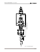
How to change the input sensitivity:
1. Turn off the amplifier and disconnect its power cord
from the AC mains power receptacle.
2. Remove the
P.I.P.
module (two screws).
3. Locate the sensitivity switch access hole inside the
chassis opening as shown in Figure 4.3. It is
located just above the phone jack inputs.
4. Set the switch to the desired position noted on the
label for the access hole. The position toward the
front panel sets the sensitivity to 1.4 volts for
standard 1 kHz power, the middle position
provides 26 dB gain, and the back position sets the
0.77 V
26 dB
SENSITIVITY SWITCH INSIDE ACCESS HOLE
GROUND LIFT SWITCH
1.4 V
UNBALANCED
INPUT WIRING
BALANCED
INPUT WIRING
THIS AMPLIFIER IS EQUIPPED WITH SELECTABLE INPUT SENSITIVITY. REMOVE P.I.P. MODULE TO ACCESS SENSITIVITY SWITCH.
CH-2 CH-1
+
–
TIP
RING
SLEEVE
GND
+
TIP
SLEEVE
GND
INPUTS
(MONO)
INPUT GROUND LIFT
(AFFECTS PHONE INPUTS ONLY.)
LIFT
Fig. 4.3 Input Sensitivity and Ground Lift Switches