500 A Huntmar Park Drive ASTi Crown® Power Amplifier User Guide Document: DOC-01-CA-UG-1 Advanced Simulation Technology inc.
Product Name: Crown® Power Amplifier Note: This document is for use with Crown Amplifiers and ASTi equipment only. Please refer to Crown’s website for more information. Crown® Power Amplifier © Copyright ASTi 2007-2012. Restricted Rights: Use, duplication, or disclosure by the Government is subject to restrictions as set forth in subparagraph (c)(1)(ii) of the Rights in Technical Data and Computer Software clause at DFARS 252.227-7013. This material may be reproduced by or for the U.S.
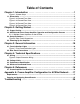
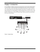
Table of Contents Chapter 1: Introduction . . . . . . . . . . . . . . . . . . . . . . . . . . . . . . . . . . . . . . . 1 Figure 1: System Setup ............................................................................................................. 1 1.1. Dimensions ............................................................................................................................. 2 Figure 2: 4-Channel Front View ................................................................................
ii
ASTi Crown® Power Amplifier User Guide (Ver. 1, Rev. F) Chapter 1: Introduction The Crown® Power Amplifier provides the user with the power to drive passive audio loudspeakers. Each amplifier is a network component that integrates with ASTi’s ACENet. ACENet provides a low latency, network based audio and I/O distribution architecture for ASTi’s Telestra 4 ACE communications and sound modeling equipment and software. The amplifier offers a full range of indicators for accurate diagnostics.
ASTi Crown® Power Amplifier User Guide (Ver. 1, Rev. E) 1.1. Dimensions Crown Amplifier Depth Width Height CTs 4200 16.25 In. 41.3 cm 19 In. 48.3 cm 3.5 In. 8.9 cm CTs 8200 16.25 In. 41.3 cm 19 In. 48.3 cm 5.25 In. 13.
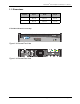
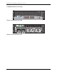
ASTi Crown® Power Amplifier User Guide (Ver. 1, Rev. F) CTs 8200 8-Channel Crown Amp Figure 4: 8-Channel Front View + - + dB 0 dB 0 dB 0 dB 0 dB 0 dB 0 dB 0 8 - 8 + 8 + 8 - 8 + CLASS 2 - 8 + 8 + - 8 DUAL + dB 0 ~ ~ + - - - + + + + DUAL - - - + + + Figure 5: 8-Channel Rear View Copyright © 2012 Advanced Simulation Technology inc.
ASTi Crown® Power Amplifier User Guide (Ver. 1, Rev. E) Chapter 2: Getting Started WARNING: Before amplifier installation, ensure that your amplifier is not connected to power and all control levels are turned down (counter clockwise). 2.1. Proper Cooling Do not block any of the amplifier ventilation vents. When using an equipment rack, mount the units directly on top of each other. Do not block rear, front, or side air vents. The side walls of the rack should be a minimum of two inches (5.
ASTi Crown® Power Amplifier User Guide (Ver. 1, Rev. F) 2.2. ACENet and Crown Power Amplifier Operation and Configuration Process Each power amplifier connected to a Telestra 4 Target forms part of the ASTi networked ACENet audio distribution architecture, and hence behaves a little differently from a simple analog power amplifier at start-up.
ASTi Crown® Power Amplifier User Guide (Ver. 1, Rev. E) ASTi recommends that users limit themselves to the basic operation of the Crown power amplifiers, however we do recognize that there are many sophisticated capabilities available within the embedded functionality of the amplifiers via the Crown HiQnet. Please contact ASTi before attempting to utilize any of the extended features of these amplifiers to ensure that there is no conflict with required ASTi configuration settings.
ASTi Crown® Power Amplifier User Guide (Ver. 1, Rev. F) 2.2.1. Multiple Crown Amplifiers on the ACENet All Crown amplifiers come pre-configured with the same IP address and when using two or more on the same ACENet network they will not function properly in the System Architect software until one IP address is changed. ASTi recommends changing all IP addresses if using multiple Crown amplifiers on the same ACENet network.
ASTi Crown® Power Amplifier User Guide (Ver. 1, Rev. E) 2.3. Setup Procedure 1. Connect the power cord into the AC Power Cord Connector. 2. Remove the Output Connector’s cover plate and connect the speakers to the output connectors. 3. The dual RJ45 connectors allow a Primary & Secondary Ethernet port to the 100 Mbps Ethernet network. Use the Primary or Secondary port and a Category 5 cable to connect to the ACENet switch. 4.
ASTi Crown® Power Amplifier User Guide (Ver. 1, Rev. F) 2.4. Powering Up the Amplifier Important: Complete section 2.1. Setup Procedure before proceeding with this section. When turning on the amplifier for the first time follow the steps below. 1. Turn down the levels of the audio source. 2. Turn on the Power switch. The power indicator should illuminate. 3. Turn up the audio source levels. 4.
ASTi Crown® Power Amplifier User Guide (Ver. 1, Rev. E) Chapter 3: General Information 3.1. Front Indication Lights • Bridge Mode Indicator – illuminates yellow when the channel pair is set to the “Bridge” position. If the bridge mode is changed while the amplifier is powered on it must be powered off and back on to reset the mode. • Ready Indicator – illuminates green when the channel is initialized and ready to produce audio output.
ASTi Crown® Power Amplifier User Guide (Ver. 1, Rev. F) 3.2. Rear Panel Connections Caution: Manual selection of a ‘preset’ (via the rear panel ‘preset’ switch) will almost certainly cause the amplifier to cease communication with the Target (since the required ACENet configuration data will not be available in the selected preset).
ASTi Crown® Power Amplifier User Guide (Ver. 1, Rev. E) • Channel Level Controls – act as the overall master gain control for each channel in all operational modes. The exact setting required for any specific installation will depend on a number of factors including speaker placement, speaker sensitivity, size of the space being driven, and of course the required sound level required from the system.
ASTi Crown® Power Amplifier User Guide (Ver. 1, Rev. F) Chapter 4: Technical Specifications 4.1. Wiring Select the appropriate size of the wire based on the distance from the amplifier to the speaker. Distance Wire Size up to 25 ft. (7.6 m) 16 AWG 26-40 ft. (7.9-12.2 m) 14 AWG 41-60 ft. (12.5-18.3 m) 12 AWG Over 60 ft. (18.3) 10 AWG Warning: Never connect the speaker return to the chassis of the amplifier, or damage to the amplifier may result. Never use shielded cable for output wiring.
ASTi Crown® Power Amplifier User Guide (Ver. 1, Rev. E) 4.2. Voltage Limits Under-Voltage Limit Over-Voltage Limit 120 VAC units 108 VAC 132 VAC 220V / 230V / 240V units 198 VAC 264 VAC Models 4.3. Performance Specification Performance CTs 4200 CTs 8200 Frequency Response (at 1 watt, 20 Hz – 20 kHz) 0.5dB 0.5dB Signal to Noise Ratio below rated power (20 Hz to 20 kHz) 100 dB unweighted 100 dB unweighted Total Harmonic Distortion (THD) at 1 watt, from 20 Hz to 20 kHz < 0.05% < 0.
ASTi Crown® Power Amplifier User Guide (Ver. 1, Rev. F) 4.4. Minimum Guaranteed Power CTs 4200 Minimum Guaranteed Power (in watts, 0.1% THD) 120VAC, 60 Hz units Dual Mode Channels Driven 4 2 1 1 kHz 20 Hz - 20 kHz 1 kHz 1 kHz 20 Hz - 20 kHz 4 Ohm 260 215 270 270 225 8 Ohm 180 190 210 220 210 CTs 8200 Minimum Guaranteed Power (in watts, 0.
ASTi Crown® Power Amplifier User Guide (Ver. 1, Rev. E) Chapter 5: References For more information please read the following Crown® documents: • Crown® Operation Manual for CTs 4200 and 8200 Multi-Channel USP/CN Series • Amplifier Application Guide To obtain the latest versions of these documents please visit the Crown® website at www.crownaudio.com. 5.1.
ASTi Crown® Power Amplifier User Guide (Ver. 1, Rev. F) Appendix A: Crown Amplifier Configuration for ACENet Network Requirements • Crown® Amp connected to the ACENet Network • HiQnet System Architect® software (download at http://hiqnet.harmanpro.com). Be sure to download the latest version.
ASTi Crown® Power Amplifier User Guide (Ver. 1, Rev. E) 3. Navigate to Tools > Network Troubleshooter and select it. 4. The following screen will appear, select 'Next'. 18 Copyright © 2012 Advanced Simulation Technology inc.
ASTi Crown® Power Amplifier User Guide (Ver. 1, Rev. F) 5. Select the network interface of your computer that is connected to the amplifier and select “Next.” 6. Wait as the system detects devices over the network. Copyright © 2012 Advanced Simulation Technology inc.
ASTi Crown® Power Amplifier User Guide (Ver. 1, Rev. E) 7. As the system gathers information, the computer syncs the subnet mask of the amp. 8. The following screen will appear, select 'Next'. 20 Copyright © 2012 Advanced Simulation Technology inc.
ASTi Crown® Power Amplifier User Guide (Ver. 1, Rev. F) 9. The following screen will appear, check the box and select 'Next'. 10. The following screen will appear, select 'Next'. Copyright © 2012 Advanced Simulation Technology inc.
ASTi Crown® Power Amplifier User Guide (Ver. 1, Rev. E) 11. The following screen will appear, select 'Finished'. The amplifier(s) are now readdressed to be on the same subnet as the computer running this software. 12. A Crown® Amp icon will appear for each amp on the network. Double-click the Crown® Amp to make adjustments. 22 Copyright © 2012 Advanced Simulation Technology inc.
ASTi Crown® Power Amplifier User Guide (Ver. 1, Rev. F) 13. Make adjustments to the amp configuration to set it up for your requirements. 14. After making changes, the 'Store' button will illuminate in yellow. Select the 'Store' button to save the changes to the preset. Important: Keep a close eye on the CPU usage indicators shown in the lower left of the above pictures. Adding filters and settings use CPU resources which are finite.
ASTi Crown® Power Amplifier User Guide (Ver. 1, Rev. E) 15. Store as Preset 1 and click 'Ok.' Important: Always save and load files to Preset 1. Preset 1 is the default and will automatically run on the amp after it boots. 16. Select File > Save > Preset File. 17. Select '1 - Preset 1' and select 'Ok'. 18. Click “Select” to configure the filename and path of the saved preset. 19. Click “Ok.” The configuration is now complete. 24 Copyright © 2012 Advanced Simulation Technology inc.
ASTi Crown® Power Amplifier User Guide (Ver. 1, Rev. F) Opening and Assigning Saved Presets 1. To open a preset, navigate to File > Open > Preset File. 2. Select Preset1. 3. Check the “Copy preset…” box. 4. Select the preset file to load into your selected preset. 5. Click “OK.” Copyright © 2012 Advanced Simulation Technology inc.
ASTi Crown® Power Amplifier User Guide (Ver. 1, Rev. E) Troubleshooting Any transparent devices that show up in the main window are devices that have been recognized on the network at some point but are not currently connected to the network. Check the amp power and ACENet connection. 26 Copyright © 2012 Advanced Simulation Technology inc.