
User Manual


Page 15
Com-Tech 200/400/800/1600 Power Amplifiers
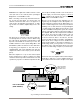
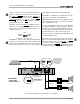
Fig. 3.6 Wiring for Bridge-Mono 70 Volt Mode (140 Volt Output)
COM
+
–
+
140 VOLT STEP-DOWN
TRANSFORMERS
16, 8, OR 4 OHM
16, 8, OR 4 OHM
140 VOLT LINE
MIXER
LOUDSPEAKERS
Com-Tech Amplifier
CHANNEL 1
BRIDGE-MONO
70 VOLT MODE
(140 VOLT OUTPUT)
TURN OFF THE AMPLIFIER
BEFORE CHANGING
THE DUAL/MONO SWITCH.
TURN OFF THE AMPLIFIER
BEFORE CHANGING THE
OUTPUT MODE SWITCHES.
WARNING: BOTH CHAN-
NELS MUST BE SET TO
70 VOLT MODE.
COM
+
–
+
DO NOT
USE
TURN OFF CHANNEL 2 (CCW)
IN BRIDGE-MONO MODE.
DO NOT USE
THE GROUND
TERMINALS
BRIDGE
MONO
DUAL
PARALLEL
MONO
BB
Programm able
Input Processor ( P. I.P.)
–+
CH-2 I NPUT
–+
CH-1 I NPUT
70
VOLT
70
VOLT
8/4
OHM
8/4
OHM
CH1
CH2
CH-2 CH-1
0
dB
.5
1
2
3
4
5
6
7
8
910
11
13
15
17
19
21
25
32
∞
0
dB
.5
1
2
3
4
5
6
7
8
910
11
13
15
17
19
21
25
32
∞
P
R
E
S
S
R
E
S
E
T
PUSH TO RESET
minals (see Figure 3.6 and the middle illustration in
Figure 3.7). The
positive lead from the load connects to
the
positive channel 1 terminal, and the negative (or
ground) lead from the load connects to the
positive
channel 2 terminal. Do not connect the output
grounds (
). Also, the load must be balanced (neither
side shorted to ground).
CAUTION: Only connect
balanced equipment (meters,
switches, etc.) to the Bridge-Mono output. Both sides of
the line must be isolated from the input grounds or os-
cillations may occur.
BRIDGE
MONO
DUAL
PARALLEL
MONO
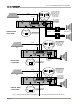
P A R A L L E L - M O N O
Parallel-Mono mode is used to drive loads with a total
impedance of less than 4 ohms when using 8/4 ohm
output mode (see
Bridge-Mono
if the load is greater
than 4 ohms). This mode can also be used to drive a
single high-powered 70 volt constant voltage line.
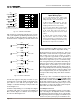
Parallel-Mono installation is very different from the
other modes and requires special attention.
WARNING: Both channels must be configured for the
same output mode (8/4 ohm or 70 volt) before switch-
ing to Parallel-Mono mode.
To select Parallel-Mono mode, turn off the amplifier
and slide the dual/mono switch to the left (as you face
the back panel). Connect the input signal to channel 1
only. The channel 2 input jack and level control are by-
passed in this mode, so they should not be used.
Note: It is normal for the channel 2 IOC indicator to stay
on in Parallel-Mono mode.
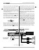
Connect the load to the channel 1 output as shown in
Figure 3.7 (top and bottom illustrations). The
positive
lead from the load connects to the
positive (+) terminal
of channel 1, and the
negative (or ground) lead from
the load connects to the
ground ( ) terminal of channel
1. Finally, install a jumper wire of at least 14 gauge be-