OIL FIRED FURNACE INSTALLATION AND OPERATION MANUAL WITH USERS INFORMATION SECTION MODEL: OH6FA072D48B OH6FA072D48R OH6FA072D48N OH6FA072DV4B OH6FA072DV4R OH6FA072DV4N OH6FX072DV4R OH8FA119D60B OH8FA119D60R OH8FA119DV5B OH8FA119DV5R χ WARNING: IF THE INFORMATION IN THESE INSTRUCTIONS IS NOT FOLLOWED EXACTLY, A FIRE OR EXPLOSION MAY RESULT CAUSING PROPERTY DAMAGE, PERSONAL INJURY, OR LOSS OF LIFE.
CONTENTS SECTION PAGE I. SAFETY SECTION A. CODES AND CLEARANCES B. MAKE-UP AIR 1 3 4 II. GENERAL INSTRUCTIONS A. CHIMNEY B. VENTING C. DRAFT REGULATORS D. DUCT WORK/AIR CONDITIONING E. AIR FILTER(S) F. LIMIT POSITION AND LOCATION G. BURNER INSTALLATION H. BURNER SPECIFICATIONS AND APPLICATIONS I. OILTANK AND PIPING J. OIL FILTER K. ELECTRICAL WIRIING L. BLOWER SETUP M. BLOWER CONTROLLER INFORMATION FOR PSC MOTOR N. STARTUP PROCEDURES 5 6 10 11 11 15 17 18 19 22 23 23 27 35 40 III.
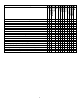
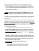
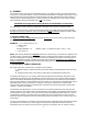
ii 0 0 1 1 7 7 1 1 2 2 9 9 0 7 2 Burner A A A A 9 10 11 12 Clg Airflow Cap. 8 Clg Airflow Cap. 7 Blower Type 6 Capacity F F F F 5 Capacity 6 6 8 8 Flue Heat Exchanger Identifier H H H H 4 Capacity O = Oil H = Highboy D = Downflow 6 = Heat Exchanger Size Identifier F = Front R = Rear A = Single Stage X = 2-Stage Heating Capacity MBTUH (000's) with factory installed nozzle D = Direct Drive Clg. Airflow: Example = 48MBTUH = 4 tons @ 400cfm/ton Clg.
I. SAFETY SECTION This page and the following contains various warnings and cautions found throughout the Oil Furnace Manual. Please read and comply with the statements below. χWARNING AND CAUTIONS: χWARNING: This furnace is not to be used as a construction heater. See Page 3 χWARNING: The predetermined limit locations on all of the Thermo Pride oil fired furnaces have been tested and approved by Thermo Products, LLC.
2
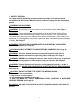
The entire text of these instructions must be read and understood, before installing the appliance. It is the installer's responsibility to do the following: 1. Inform and demonstrate to the user, the correct operation and maintenance of the appliance, as explained in the Homeowner/User Information and Routine Maintenance section of this manual. 2. Inform the user of the hazards of flammable liquids and vapors and to remove such liquids and vapors from the vicinity of the appliance. 3.
b. Non-combustible material: “...material that is not capable of being ignited and burned; such as material consisting entirely of, or a combination of, steel, iron, brick, concrete, slate, asbestos, glass, and plaster.” : Carefully read and thoroughly understand the following guidelines and warnings before continuing with the installation of this appliance. Failure to follow these guidelines can cause improper and unsafe operation of this appliance.
II. GENERAL INSTRUCTIONS - READ BEFORE START OF INSTALLATION 1. The heating output capacity of the furnace proposed for installation should be based on a heat loss calculation made according to the manuals provided by the Air Conditioning Contractors of America (ACCA) or the American Society of Heating, Refrigeration and Air Conditioning Engineers, Inc. (ASHRAE). 2. All local codes and/or regulations take precedence over the instructions in this manual and should be followed accordingly.
A. CHIMNEY: The furnace must be connected to an adequate chimney or an approved vent in accordance with these instructions. An adequate chimney is one that is sealed and lined with the capability of producing a (-).04" WC flue draft and having the capacity to handle the amount of stack gases that are introduced into it. A chimney with an internal construction of corrosion resistant tile, stainless steel, or some other material that will withstand flue gas temperatures up to 900°F is required.
must be used, such as a Class "A" triple wall or insulated metal chimney. A liner will act as an insulator and reduce the stack gas temperature loss. Insulation may be added around the liner for further temperature stability. If the chimney is on the home's exterior or passes through a sizable, unheated area of the building, such as a porch, high ceiling attic, etc., and condensing occurs, the chimney must be insulated around its exterior to help the flue hold its temperature.
Fig. 4: Proper insertion of the vent connector in the chimney. 5. PROPER CHIMNEY BOTTOM LEVEL: In cases where the chimney extends to the basement floor, the draft can usually be improved by filling the base of the chimney with sand to within 12 inches of the vent connector pipe after relocating the clean-out door. (See Fig. 5). Fig. 5: Suggested method to improve chimney draft. 6. TIGHT JOINTS: All joints of the chimney must be tightly sealed.
Fig. 6: Suggested method to accommodate vent connector passage through a wall composed of a combustible material. Fig. 7: Alternate constructions that allow reduced clearances to combustible materials. REDUCTION OF CLEARANCES WITH SPECIFIED FORMS OF PROTECTION: Type of protection applied to and covering all surfaces of combustible material within the distance specified as the required clearance with no protection unless otherwise noted, all dimensions in inches, refer to Fig. 7.
The vent connector pipe between the furnace and chimney shall be of equal diameter as the flue outlet of the furnace. The vent connector pipe must be made of 24 gauge (or thicker) corrosion-resistant steel. The vent connector pipe should be as short as possible and installed so that it has a continuous rise from the furnace to the chimney.
The side wall vent may be installed either through the knock-out on the right or left side casing of the unit or vertically out the top opening of the vestibule. The combustion air inlet can be installed through the either the lower left side casing knockout or the lower right side casing knockout. C. DRAFT REGULATORS: Note: Do not use with Direct Vent application. A draft regulator is supplied with the furnace and should be installed according to the regulator manufacturers recommendations.
Airflow Requirements and Sizing of Duct Work: The duct system must be sized and installed by a qualified installer or service person, following the design standards of the Air Conditioning Contractors of America (ACCA) or the American Society of Heating, Refrigeration, and Air Conditioning Engineers (ASHRAE). This furnace has been designed to operate against a maximum external static pressure of 0.5 in. W.G. This is equivalent to 0.1 in. W.G. supply, and 0.1 in. W.G. return, and 0.3 in. W.G.
the supply and return air systems added together cannot exceed the maximum external static pressure that can be supplied by the appliance blower. f. Determine the required flow rate for each branch of the supply and return air systems. The total airflow rate, by adding the airflow rate of each branch of the supply system, must equal the minimum required airflow rate (refer to part 3, above).
Table 3: Suggested Duct Sizes for Homes, Quiet Offices, Or Similar Installations (Based on a 0.1 in. W.G. static pressure drop per 100 ft. of duct.) 7. The supply and return air ducts, or flexible joints, should be carefully secured and sealed to the appliance housing to prevent air leakage from, or into, the duct system. For best performance, insulate the outside surfaces of the ducts to reduce heat loss from, or heat gain to, the ducts. 8.
SIZING THE DUCT WORK FOR A COMBINATION HEATING AND COOLING SYSTEM: Two formulas must be used in determining the CFM requirements of a combustion heating and cooling system. 1. HEATING CFM: HEAT OUTPUT OF FURNACE (BTUH) 1.1 X TR (TEMPERATURE RISE, °F) = HEATING(CFM) EXAMPLES: A. 110,000 BTUH OUTPUT 1.1 X 85°F TR = 1176 CFM FOR HEATING B. 110,000 BTUH OUTPUT 1.1 X 70°F TR = 1429 CFM FOR HEATING 2. COOLING CFM: 400 CFM X COOLING TONNAGE (12,000 BTUH PER TON)=AIRFLOW FOR COOLING(CFM) EXAMPLES: A.
Connect the return air plenum to the filter rack and slide the filter into place. Dimensions for adapting the return air plenum to the filter rack are provided (See Fig. 10a & 10b). Fig. 10a: A typical filter rack and dimensions for the OH6 furnace. Fig. 10b: A typical filter rack and dimensions for the OH8 furnace. : Failure to comply with minimum filter installation requirements may affect the performance and/or void the warranty on this unit.
Maximum Air Velocity (ft/min) Filter Type *Thermo Products Supplied Permanent Standard Permanent Disposable Model Number OH6 OH8 600 384 in² 480 in² 500 461 in² 576 in² 300 768 in² 960 in² Table 4: Minimum Required Filter Area (in square inches) * The Thermo Products supplied filter can be cut to size to fit other filter retention systems as long as the minimum size requirement is met.
G. BURNER INSTALLATION: NOTICE: Remove all cardboard packing from around chamber before installing burner. The oil burner will mount on three stud mounting bolts on the lower mounting plate covering the opening in the front of the heat exchanger. The end of the burner tube should be inserted no further than 1/4 inch back from the inside surface of the combustion chamber. A distance further than 1/4 inch back from the inside chamber wall may cause impingement and sooting.
Fig. 13: Burner insertion illustration (Top view) When mounting the burner, the mounting plate (Fig. 12) must be removed to provide access to the area in front of the combustion chamber. A fiber insulating sleeve or amulet is provided on the burner tube of specific Thermo Pride burners.(see Fig. 13). See Thermo Pride burner application chart for type of insulator.
OIL NOZZLE CAPACITY CHART UNITS OH6FA060D*** OH6FA072D*** OH6FA090D*** OH8FA101D*** OH8FA119D*** OH8FA132D*** NOZZLE SIZE (GPH) Beckett Riello EQUIVALENT HEAT INPUT RATE* (BTU/HR) .50 .60 .75 .85 1.00 1.10 .50 .60 .70 .75 .85 1.00 70,000 85,000 106,250 119,000 140,000 156,250 EFFECTIVE HEATING CAPACITY** (BTU/HR) 60,000 73,000 90,000 101,000 119,000 132,000 Table 7: Oil nozzle capacity All rates shown achieved with 120 PSIG pump pressure for Beckett and 140 PSIG pump pressure for Riello.
For more specific burner information, specifications or service information, reference the training manual enclosed with each Riello burner or contact: Riello Corporation of America, 5 Pond Park Road Hingham, Massachusetts 02043 Phone: (617) 749-8292 2 STAGE FIRING RATES CAPACITY HIGH CAPACITY FIRING RATE HIGH FIRE NOZZLE SIZE Riello .70 X 45° W LOW FIRE LOW CAPACITY HIGH FIRE .
Verify that the installed burner is lightly leaned towards the button. (See figure 14-1) The burner is designed to allow entry of the flexible oil-lines on either side of the burner. I. OIL TANK AND PIPING: : All local codes and ordinances take precedence with regard to selection and installation of oil storage tank and oil supply (and return) lines.
the pump. Pitching the line upward toward the tank will help prevent the formation of air pockets in the line. NOTICE: An oil safety valve or a delayed-action, solenoid valve should be installed in the oil supply line of all gravity-fed systems. When the oil tank is located below the level of the burner, it is necessary to “lift” the oil to the burner. A return line should be connected between the fuel pump and tank. This requires insertion of the "by-pass" plug into the fuel pump.
Typically, control wiring between the appliance and the indoor thermostat, and if used, electronic air cleaner or humidifier, will be required. Field wiring of control circuits should consist of copper conductors rated for at least 15 amp service with an insulation temperature rating conforming to Type T wire, 35°C temperature rise. Depending upon code requirements, rigid or flexible conduit is recommended, and may be required.
in conjunction with a humidistat to control a humidifier. These terminals are energized whenever the blower is active. Figure 15: The Fan Control Module NOTICE: It is important to confirm that the operating voltage of the humidifier or EAC being installed matches the output of this control. If not, a field supplied relay or transformer may be necessary to provide the proper control and supply voltage for the accessory being installed.
Figure 16: Heat Anticipator Adjustment Scale In many cases, this setting can be found in the thermostat installation instructions. If this information is not available, or if the correct setting is questioned, the following procedures should be followed: Preferred method of adjustment: Using an analog ammeter on the lowest scale, such as an Amp Check, connect the meter across terminals “R” and “W” on the sub-base (“RH” & “W” on an isolating thermostat sub-base).
This formula can be used to calculate the correct setting for the adjustable heat anticipator: Ammeter reading No. of wire loops = Anticipator Setting. Or in this case, _2.5 A. = 0.25 A. (Anticipator Setting) 10 4. Adjust the position of the anticipator indicator to match the calculated ammeter setting. If a slightly longer cycle is desired, the pointer should be moved to a higher setting. Slightly shorter cycles can be achieved by moving to a lower setting. 5.
Heating Speed Set-ups OH6FA072DV4 Furnace Motor Current Draw (Amps/ / Watts) vs. External Static Pressure (in W.C.) BTUH Fan Control SW 1 Switch Settings 3-OFF 2-OFF 1-OFF Factory SW1 Switch Settings Heating CFM Low Fire Med Fire High Fire 60,000 72,000 90,000 Aprox. Rise Aprox. Rise Aprox. Rise (F0 ) (F0 ) (F0 ) 0.2 0.4 0.6 0.9/75 1.4/123 1.7/156 740 75o 3-OFF 2-OFF 1-ON 812 68o 82o 1.0/86 1.5/136 1.9/172 3-OFF 2-ON 1-OFF 883 63o 76o 1.1/95 1.6/143 2.
Heating Speed Set-ups OH8FA119DV5 Furnace Motor Current Draw (Amps / Watts) vs. External Static Pressure (in W.C) Low Fire Med Fire High Fire BTUH 101,000 Fan Control SW 1 Switch Heating Settings CFM 3-OFF 2-OFF 1-OFF 119,000 132,000 Aprox. Aprox. Aprox. Rise (F0 ) Rise (F0 ) Rise (F0 ) 0.1 0.2 0.3 0.4 0.5 0.6 0.7 1.4/124 1.8/161 2.1/190 2.4/220 2.7/240 3.1/286 3.4/317 1202 78o 3-OFF 2-OFF 1-ON 1315 71o 84o 1.8/158 2.1/190 2.3/209 2.7/250 3.1/285 3.4/311 3.
Heating Speed Set-ups ( 2 – Stage ) OH6FX072DV4 Figure 18-2: ECM 2-stage blower motor speed chart 30
Cooling Speed Set-ups OH6F*072DV4 Furnace Motor Current Draw (Amps / Watts) vs. External Static Pressure (in W.C) Air Flow Fan Control SW 1 Switch Settings 6-OFF 5-OFF 4-OFF 6-OFF 5-OFF 4-ON 6-OFF 5-ON 4-OFF 6-OFF 5-ON 4-ON 6-ON Factory SW1 Switch 5-OFF 4-OFF Settings Clg. Tonnage Cool Continuous 0.2 0.4 0.6 2 799 500 0.9/79 1.5/128 1.9/170 2.5 1017 508 1.3/112 1.9/171 2.6/238 3 1210 605 1.9/172 2.4/226 3.0/279 3.5 1404 702 2.6/237 3.4/320 3.8/370 4 1622 799 4.1/390 4.
Cooling Speed Set-ups OH8FA119DV5 Furnace Motor Current Draw (Amps/Watts) vs. External Static Pressure (in W.C.) Air Flow Fan Control SW 1 Switch Settings Clg. Tonnage Cool Continuous Dehum 0.1 0.2 0.3 0.4 0.5 0.6 0.7 2 800 500 557 0.8/69 1.0/88 1.3/112 1.5/132 1.7/147 1.9/169 2.2/194 6-OFF 5-OFF 4-ON 2.5 1018 509 703 1.1/92 1.4/123 1.7/148 1.9/170 2.3/207 2.6/235 2.8/253 6-OFF 5-ON 4-OFF 3 1212 606 848 1.4/127 1.9/166 2.2/194 2.4/218 2.8/251 3.1/287 3.
For PSC systems, the ½ hp motor is equipped with 4 speeds. The unit is set for mid-fire temp rise @ 65ºF. See table for proper blower motor set up: OH6FA072D48 ALTERATIONS REQ’D FOR A/C @ DESIGN EXTERNAL STATIC PRESSURE COOLING UNIT Recommended CLG Speed HTG Speed by Input Low Fire Mid Fire High Fire 24,000 Low ML MH Low 30,000 Low ML MH Med Low 36,000 Low ML MH Med High 42,000 Low ML MH Med High 48,000 Low ML MH High Speed Tap\ Static Pressure Furnace Airflow (CFM) vs.
OH8FA119D60 ALTERATIONS REQ’D FOR A/C @ DESIGN EXTERNAL STATIC PRESSURE COOLING UNIT Recommended CLG Speed HTG Speed by Input Low Fire Mid Fire High Fire 36,000 L/ML ML/MH MH/H Low (L) 42,000 L/ML ML/MH MH/H Med Low (ML) 48,000 L/ML ML/MH MH/H Med High (MH) 60,000 L/ML ML/MH MH/H High (H) Furnace Airflow (CFM) vs. External Static pressure (in. WC.) Speed Tap\ Static Pressure 0.1 0.2 0.3 0.4 0.5 0.6 0.
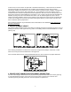
M. BLOWER CONTROLLER INFORMATION FOR PSC MOTOR (Note: for ECM blower controller information see: ECM Operation Manual document # Mo-440) TERMINAL DEFINITIONS & FIELD WIRING Burner Harness Connector P1 Pin 1- Limit switch connector. Pin 2- 120 VAC Line connection. Pin 3- Burner pilot contact. Pin 4&5120 VAC Neutral connections. Pin 6- Burner pilot contact. Pin 7&8From oil primary control. Pin 9- Limit Switch Input (LSI).
A. Inputs Power supplies Line voltage is applied between the “S1” and “N1” quick connect terminals. 24 VAC Class II Transformer secondary voltage supplied to X and C Limit switch The 120 VAC optically isolated limit switch input is connected on pin P2-1 & 9. Refer to the Heat Mode section for the control operation. Thermostat call for heat “W” 24 VAC thermostat input. A call for heat is recognized when the thermostat connects “W” to “R”.
EAC (electronic air cleaner) The control provides a 120 VAC output for an electronic air cleaner. This output is energized whenever the fan motor is energized (either low, heat or cool speed). Connection is made via male quick connect terminal labeled “EAC”. Humidifier The control provides a 120 VAC output for a humidifier. Connections are made to a male quick connect terminal labeled “FAN”.
Heat Mode When a call for heat (“W”) is received from the thermostat, if the “Cool” mode is not already active, the “T-T” terminal is energized and the blower on delay is started. The on-off pattern of DIP switch SW2 (positions 1 and 2) select one of four blower on delay values (see Table 11). When the delay time has elapsed, the “HEAT” blower speed is energized. The control remains in steady heat mode until the thermostat is satisfied.
PSC TROUBLE SHOOTING DIAGNOSTIC FEATURES The control board is equipped with 4 green Input Status LEDs and 1 red Board Status LED. These are intended to provide a quick view into furnace performance without requiring a voltmeter. The green Input Status LEDs are driven by the “Y”, “W”, “G”, and “DEHUM” inputs and are located directly below those inputs. They will light to indicate the presence of these signals.
N. STARTUP PROCEDURES: A. Heating System 1. Initial Startup: : Turn off power to furnace. Before the oil piping system is placed into service, it must have been leak tested by a qualified heating contractor. : For initial start-up of the appliance after installation, it may be necessary to purge the air out of the oil line. A qualified heating contractor should do this. Review the following items before the initial startup.
To Turn Off Oil to Appliance: i. Set the thermostat to the lowest setting and set the operating mode switch to “OFF”. ii. If service is to be performed, turn off the electrical power to the appliance. iii. Turn the manual oil shutoff valve to the “OFF” position. 2. Adjustment of Burner Combustion: : Maximum gross stack temperature must not exceed 550°F (288°C) under any circumstances. : Do not run the oil pump dry for more than five minutes, as irreparable damage may result.
Figure 19: Preliminary Adjustment of Burner Air Band and Air Shutter i. When ignition is established, make a preliminary burner air adjustment to attain a clean combustion flame. Generally, the burner bulk air band should be about 3/16 inch open and the opening of the burner air shutter set in the range of “2” to “7”, refer to Figure 19. Replace the inspection cover above the burner. j.
The setting of the fan output according to the installation should be done only through the air damper. Should you want to adjust the setting of the combustion head, with the burner running, turn the rod (1) with a 6mm wrench (2) as follows: TURN TO THE RIGHT: (SIGN + ) In order to increase the volume of air entering the combustion chamber and thus diminishing its pressure. There is a reduction of CO2 and the adhesion of the flame to the air diffuser disc improves.
Figure 22 1st STAGE ADJUSTMENT: Adjustment of air shutter: place the small plug (9) of the economizer (10) into the position I (Item A). st In this way the burner will remain permanently in the 1 stage. Loosen the nut (2), turn the screw (3) until the air shutter (1) reaches the position desired. Then lock the nut (2). Pressure regulation: this is set at 130 psi at the factory. Should such pressure be reset or changed, just turn the screw (4). The pressure gauge must be mounted in place of cap (5).
ii. CARBON DIOXIDE (CO2) OR OXYGEN (O2): Take a CO2 sample from flue passageway. It is possible to achieve readings of up to 14% CO2 (or 2% O2 ), but it is better to have a slightly lower CO2 (or higher O2) reading with zero smoke measured. To achieve a lower CO2 reading, open the air band, or shutter, on the burner until zero smoke is measured. For example, if a 13% CO2 (or 3.5% O2) is recorded at a trace of smoke, open the air shutter until zero smoke is measured with a 12% CO2 (or 4.5% O2).
a. With the oil shut off, remove the 1/8 in. NPT threaded pipe plug located on the lower rear side of the oil pump, refer to Figure 22. Attach a pressure gage, capable of measuring pressure in pounds per square inch gage, PSIG, in this opening, on the discharge side, of the oil pump. NOTICE: It may be necessary to remove the oil pump to attach the plumbing required to connect a pressure gage to the pump. b.
5. Checkout Procedure: Before any system of oil piping is finally put into service, it shall be carefully tested to assure that it is “gas-tight”, as indicated in the Heating System Initial Startup section of this manual. NOTICE: All controls on the unit should be checked for proper functioning prior to the qualified service personnel leaving the job site. Specifically the following should be checked: a.
III. USERS INFORMATION SECTION A. OIL SUPPLY: Do not allow the fuel tank to run completely empty. During the summer, keep the tank full to prevent condensation of moisture on the inside surface of the tank. If the fuel tank runs completely dry, it may be necessary to purge the lines of trapped air. Contact a qualified technician to bleed the lines and restart the burner. OIL SUPPLY VALVE: Turn the oil supply valve off if the burner is shut down for an extended period of time. B.
D. STARTING THE BURNER: 1. Turn the main service switch to "OFF" position. 2. Set thermostat substantially above room temperature. 3. Open shut-off valves in oil supply line to burner. 4. Turn service switch to furnace "ON". If burner starts and runs, but stops again on lockout, it may be necessary to bleed the lines or make burner combustion air adjustments. Contact a qualified service person to adjust and start burner. E.
IV. INSTALLER'S INSTRUCTIONS TO USER: After completing the installation, the installer shall inform and/or demonstrate to the homeowner the following items: 1. The location of these instructions. The instructions must be kept along with instructions for any accessories in the plastic pouch with the appliance. 2. The location and use of the manual oil shutoff valve and appliance electrical disconnecting device.
V. DEALER MAINTENANCE: SAFETY DURING SERVICING AND INSPECTION : Personal injury or property damage could result from repair or service of this appliance by anyone other than a qualified heating contractor. The user may only perform the activities described in the Homeowner/User Routine Maintenance section of this manual. : To avoid injury from moving parts, or electrical shock, shut off the power to the appliance before removing blower compartment door and servicing this appliance.
χWARNING: A qualified heating contractor must clean the heat exchanger. At least once a year, inspect the heat exchanger for evidence of corrosion, pitting, warpage, deterioration, and carbon (soot) build-up. A layer of soot on the inside of the heat exchanger will act as an insulator and reduce heat transfer, resulting in less heating efficiency. Also, look for loose or deteriorated gaskets and insulation around the flue pipe, the burner, and accessible areas of the heat exchanger.
Figure 24: Heat Exchanger Clean-Outs Vacuum Hose Length OH6 8FT OH8 8FT Fig. 25: Recommended method and device for cleaning inside of heat exchanger.
4. Operational Check: χCAUTION: Before troubleshooting, familiarize yourself with the start up and check out procedures NOTICE: After reassembling the appliance, check for fuel oil leakage from the supply piping. a. Check proper operation of the ignition system and for proper combustion. b. Observe the main burner flame. If the flame appears strange or abnormal in character, look for a component or components that were not reassembled correctly.
Figure 26: Location of Supply/Return Air Filter Filter replacement: To ensure an adequate replacement filter is selected, should the filter require replacing, refer to Table 4, in Air Filters section of this manual, for the minimum filter areas required for different types of available filters. NOTICE: Remind the homeowner of the importance of monthly filter inspections during operation to ensure maximum operating efficiency. G.
ON STARTUP: 1. Have system inspected and started by a qualified heating contractor. 2. Check oil level in tank. If the tank has not been filled with fresh oil, inspect the remaining oil for signs of contamination with water, algae, dirt or other impurities. If excessive, consult your oil supplier for recommendations. 3. Change the oil filter cartridge and clean the canister. 4. Set the room thermostat above room temperature. 5. Open all valves in the oil supply line. 6.
: Do not use this appliance if any part has been under water. Immediately call a qualified service technician to inspect the furnace and to replace any part of the control system and any oil control that has been under water. : Should overheating occur, or the oil supply fail to shut off, shut off the electrical power to the appliance, before shutting off the manual oil valve.
Beckett Burner Riello Burner Figure 28: Location of oil primary control reset button If this action does not reactivate the unit, contact a qualified service agency for assistance. In general, if the thermostat is set in the heating mode, the heating system functions entirely automatically. However, under certain circumstances, the appliance may not be able to fire the burner.
1. Check for 115VAC line supply voltage to the furnace. If there is no supply voltage, check fuses and service switch. χCAUTION: When testing electrical equipment, always follow standard electrical procedures. 2. Make sure thermostat is calling for burner operation. 3. Check oil supply and make sure all valves are open. A. DIAGNOSTICS: To assist in troubleshooting this appliance, it is equipped with an integrated safety and ignition control with diagnostics.
3. Check the resistance across the cad cell pins with the cell covered (protected from exposure to ambient light). The resistance should be greater than 20,000 ohms. 4. If cell resistances are different from above, replace the plug-in portion of cell, (Honeywell Part No. 130367). 5. Carefully reinsert the plug-in portion of the cad cell into the receptacle.
VIII.
62
IX.
64
65
66
67
COMBUSTION AND EFFICIENCY TESTING FOR THERMO PRIDE OIL FIRED CENTRAL FURNACES. Complete this form for each Thermo Pride furnace installed. Read instruction manual carefully before making tests. Retain this form with furnace. CUSTOMER NAME ADDRESS CITY, STATE HEATING BURNER MODEL NO. AIR SHUTTER OPENING BLAST TUBE LGTH. INS. SYSTEM COMBUSTION CHAMBER CONDITION % OF MAX.
Appendix – A Replacement Parts: Replacement Parts for OH6FA072D** 69
Replacement Parts for OH8FA119D** 70
Appendix – B Wiring Diagrams OH6FA072D48 PSC Wiring Diagram 71
OH6FA072DV4 ECM Wiring Diagram 72
OH6FX072DV4 ECM 2-Stage Wiring Diagram 73
OH8FA1119D60 PSC Wiring Diagram 74
OH8FA1119DV5 ECM Wiring Diagram 75
76