
Instruction Manual


P.I.P.–BEQ
Page 8
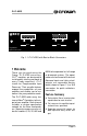
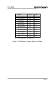
Fig. 3.2 Equalization Response for Model 25, 32, Bi-Amplified
Fig. 3.1 Equalization Response for Model 25, 32, Full Range
3 Installation
The internal jumpers and switches
of the P.I.P.-BEQ must be set prior
to installation. See the previous
section for a description of each
jumper.
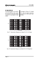
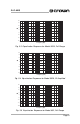
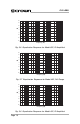
The graphs in Figures 3.1 through
3.11 show the typical frequency
response for all valid switch com-
binations.
20
5
0
-5
-10
-15
-20
dB
10 100 1000 10000
Frequency (Hz)
100000
10
15
20
5
0
-5
-10
-15
-20
dB
10 100 1000 10000
Frequency (Hz)
100000
10
15