
User Manual

DCi Series Power Amplifiers
page 13
Operation Manual
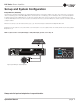
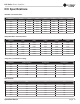
Indicators:
Fault Indicator (red): Flashes when the amplifier output channel has stopped operating.
(See Page 16 Troubleshooting.)
Thermal Indicator (red): Illuminates when the channel reaches 80 degrees Celsius, indicating the onset of
protection compression.
Clip Indicator (red): Illuminates when any of the following conditions are present: Onset of audible clipping,
clipped signal detected at input, clipped signal detected at output, engagement of TLC protection circuit.
Level and Signal Indicators (green): Three LEDs indicate signal presence and level as follows: -10 = 10 dB
below rated output -20 = 20 dB below rated output Signal = -40dBU input level
Ready Indicator (green): When this indicator is activated, the amplifier is ready to pass audio.
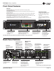
Cooling Vent Grille
Provides cooling air flow.
Do not block or cover
these vents.
Power Button
Power Ring Indicator
(Green) - Illuminates when
the amplifier is plugged
into a wall outlet with
acceptable power.
Power Indicator (blue)
Illuminates when the amplifier is ON and
acceptable AC line voltage is present.
Blinks when AC line voltage is outside
±10% range.
Flashes for 4 seconds if Power button
pressed when amplifier is in sleep mode.
(page 16)
Bridge Mode Indicator (yellow)
Illuminates when when Bridge Mode is
activated for the channel pair, only odd
number channel will be active
Note: Eight channel model shown. Indications per channel pair are identical for 2 and 4 channel models.
Data Indicator (yellow)
Illuminates when data present
on the network. (Not used in
analog input versions.)
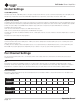
Global Setting DIP
Switches
Settings for 70/100 VRMS
(Hi-Z operation) operation
mode, AMP STATUS and
POWER SAVE. These DIP
switches affect all output
channels. (Refer to Page 14)
Cooling Fan Outlet
Outlets for cooling air
flow. Do not block or
cover these outlets.
Auxiliary Connector
3-pin plug-in type connector,
Enables SLEEP mode and
monitoring of AMP STATUS
unless the amplifier is in any of
these conditions: OFF, SLEEP, or
FAULT. (see Page 14)
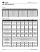
Output Connectors
One four-pole touch-proof
terminal strip per channel pair.
Accepts up to 10 AWG wire or
terminal forks.
Channel Pair DIP
Switches
One block of three DIP
Switches for each channel
pair. Allows selection of Lo-Z
or Hi-Z operation per channel
and bridging of designated
channel pairs.
(Refer to Page 14)
Power Fuse
F20AH 250V, replace with
same type fuse. LittelFuse
314 Series.
AC Power Inlet:
Standard IEC type 320 inlet
for detachable connector
100 - 240 V~
Input Attenuators
One 21-position detented
porentiometer per
channel. Logarithmic
audio taper. Attenuation
range -95 dB to 0 dB
Input Connectors
One 6-pin plug-in
connector per input. High
impedance balanced.
(Refer to Page 7)
Note: This image reflects the DCi 8|
300 back panel
Front Panel Features
Back Panel Features