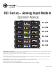
DCi Series – Analog Input Models Operation Manual DCi 8|600 DCi 8|300 DCi 4|600 DCi 4|300 DCi 2|600 DCi 2|300 Obtaining Other Language Versions: To obtain information in another language about the use of this product, please contact your local Crown Distributor. If you need assistance locating your local distributor, please contact Crown at 574-294-8000. This manual does not include all of the details of design, production, or variations of the equipment.
DCi Series Power Amplifiers Important Safety Instructions 1. Read these instructions. WATCH FOR THESE SYMBOLS: 2. Keep these instructions. The lightning bolt triangle is used to alert the user to the risk of electric shock. 3. Heed all warnings. 4. Follow all instructions. The exclamation point triangle is used to alert the user to important operating or maintenance instructions. 5. Do not use this apparatus near water. 6. Clean only with a dry cloth. 7. D o not block any ventilation openings.
DCi Series Power Amplifiers DECLARATION OF CONFORMITY Issued By: H arman International. 1718 W. Mishawaka Rd. Elkhart, IN 46517 U.S.A. European Representative’s Name and Address: David J.
DCi Series Power Amplifiers Table of Contents Important Safety Instructions ................................................................................................................ 2 Declaration of Conformity.................................................................................................................... 3 Table of Contents............................................................................................................................... 4 Welcome .....................
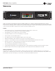
DCi Series Power Amplifiers Welcome Thank you for purchasing a new Crown DriveCore install ™ Series installation amplifier, one in a complete line of high-performance amplifiers based on exclusive DriveCore™ technology. DCi Series amplifiers are designed, engineered and manufactured to the industry’s highest quality standards, and provide system integrators with the advanced features and flexibility required for challenging 21st century installed sound applications.
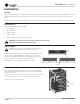
DCi Series Power Amplifiers Installation Unpacking Unpack your amplifier and inspect for any damage that may have occurred during transit. If damage is found, notify the shipping company immediately. Only you can initiate a claim for shipping damage, though Crown will be happy to help as needed. If the product arrived showing signs of damage, save the shipping carton for the shipper’s inspection. We also recommend that you save all packing materials for use if you ever need to transport the unit.
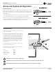
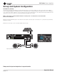
DCi Series Power Amplifiers Set-up and System Configuration Figure 3 Wire Input Connectors Crown recommends using pre-built or professionally wired balanced line (two-conductor plus shield). Balanced wiring provides better rejection of unwanted noise and hum; however, unbalanced line may also be used. For more information, refer to the Crown Amplifier Application Guide, available online at www.crownaudio.com. Use 6-pin plug-in cable ends at the amp input connectors.
DCi Series Power Amplifiers Set-up and System Configuration Connect Loudspeakers and Configure for Loudspeaker Load Determine load impedances and power requirements Before making any connections, carefully check and review the total impedance for loudspeaker systems to be connected to each amplifier output. If multiple loudspeakers are connected to one output (in series, parallel or series-parallel) for Lo-Z operation, be certain the total system impedance is within allowed specification for the output.
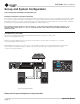
DCi Series Power Amplifiers Set-up and System Configuration Bridge Mode (16, 8, or 4 Ohm) Typical input and output wiring, along with Attenuator and Mode DIP Switch settings are shown in Figure 7. Make sure the “Hi-Z” selector switches are in the OFF (down) position and the Bridge (BRG) switch is in the ON (up) position. NOTE: Only the Hi-Z selector switches assigned to odd-numbered channels (1,3,5,7) are active in Bridge mode; switches assigned to even-numbered channels (2,4,6,8) are disabled.
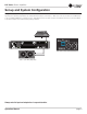
DCi Series Power Amplifiers Set-up and System Configuration Dual Mode Hi-Z (70V/100V) Typical input and output wiring, along with Attenuator and Mode DIP Switch settings are shown in Figure 8. Make sure the “Hi-Z” selector switches are in the ON (up) position and the Bridge (BRG) switch is in the OFF (down) position. A 35Hz high pass filter is selected automatically when the amplifier channel is in Hi-Z or Bridged Hi-Z mode.
DCi Series Power Amplifiers Set-up and System Configuration Bridge Mode Hi-Z (140V/200V) Typical input and output wiring, along with Attenuator and Mode DIP Switch settings are shown in Figure 9. Make sure the “Hi-Z” selector switch for the connected input channel is in the ON (up) position and the Bridge (BRG) switch for the channel pair also is in the ON (up) position. A 35Hz high pass filter is selected automatically when the amplifier channel is in Hi-Z or Bridged Hi-Z mode.
DCi Series Power Amplifiers Set-up and System Configuration Connect to AC Mains Connect your amplifier to the AC mains power source (power outlet) using the supplied AC power cord set. First, connect the IEC end of the cord set to the IEC connector on the amplifier; then, plug the other end of the cord set to the AC mains. WARNING: The third prong of this connector (ground) is an important safety feature. Do not attempt to disable this ground connection by using an adapter or other methods.
DCi Series Power Amplifiers Front Panel Features Indicators: Fault Indicator (red): Flashes when the amplifier output channel has stopped operating. (See Page 16 Troubleshooting.) Power Indicator (blue) Thermal Indicator (red): Illuminates when the channel reaches 80 degrees Celsius, indicating the onset of protection compression. Illuminates when the amplifier is ON and acceptable AC line voltage is present.
DCi Series Power Amplifiers Global Settings 70/100 VRMS (switch A) This switch selects either 70 or 100 VRMS operation for all outputs currently selected for Hi-Z mode. (See the section below, Hi-Z.) Default position is 70 V (OFF). In 70 V and 100 V mode, a voltage limiter circuit is enabled. NOTE: When bridged Hi-Z mode is implemented, selected voltages are doubled to 140V or 200V.
DCi Series Power Amplifiers Protection System Thermal Indicator If the amplifier becomes too hot for safe operation, the channel that is generating too much heat will be shut down until the temperature drops below the thermal limit. The front-panel thermal indicator will illuminate at 80 degrees Celsius, indicating the onset of compression affecting the audio signal.
DCi Series Power Amplifiers Troubleshooting CONDITION: Power indicator is off. Mains indicator is on. POSSIBLE REASON • The amplifier’s Power switch is off. “Off/Flashing/On” above means that the LED can be off, or flashing, or on. CONDITION: Power indicator is off. Mains indicator is off. POSSIBLE REASON • The power supply fuse has tripped. • The amplifier has lost AC Power. • The amplifier is not plugged in to the power receptacle. CONDITION: Power indicator is flashing.
DCi Series Power Amplifiers Troubleshooting CONDITION: Distorted sound. POSSIBLE REASON: • Load is wired incorrectly or Stereo/Bridge mode switch is set incorrectly. Check both. • Input is overloaded by a signal level that is too high. Turn down your amplifier level controls, or turn down the input signal, until the clip light goes out. Note: If the signal sounds distorted even though the Clip LED is off, the input signal may be distorted before it reaches the amplifier input.
DCi Series Power Amplifiers Troubleshooting CONDITION: No input signal. Signal indicator is not flashing even though audio is applied, and the channel is ready.. POSSIBLE REASON: • Input signal level is very low. “Off/Flashing/On” above means that the LED can be off, or flashing, or on. CONDITION: Bridge LED is lit. POSSIBLE REASON: • page 18 Amplifier is in bridge-mono mode.
DCi Series Power Amplifiers DCi Specifications Dual-Mode - All Channels Driven DCi Model Channels 2 Ohms 4 Ohms 8 Ohms 16 Ohms 70Vrms 100Vrms 2|300 2 150W 300W 300W 150W 300W 300W 2|600 2 300W 600W 600W 300W 600W 600W 4|300 4 150W 300W 300W 150W 300W 300W 4|600 4 300W 600W 600W 300W 600W 600W 8|300 8 150W 300W 300W 150W 300W 300W 8|600 8 300W 600W 600W 300W 600W 600W Minimum Guaranteed Power (20 Hz - 20 kHz) Bridge Mono Mode - All Channels Driven DCi
DCi Series Power Amplifiers DCi Specifications Dimensions DCi Model Width Height Depth 2|300 19 in. (48.3 cm) 3.5 in. (8.9 cm) 14.25 in. (36.2 cm) 2|600 19 in. (48.3 cm) 3.5 in. (8.9 cm) 14.25 in. (36.2 cm) 4|300 19 in. (48.3 cm) 3.5 in. (8.9 cm) 14.25 in. (36.2 cm) 4|600 19 in. (48.3 cm) 3.5 in. (8.9 cm) 14.25 in. (36.2 cm) 8|300 19 in. (48.3 cm) 3.5 in. (8.9 cm) 14.25 in. (36.2 cm) 8|600 19 in. (48.3 cm) 3.5 in. (8.9 cm) 17 in. (43.
DCi Series Power Amplifiers AC Power Draw and Thermal Dissipation AC Power Draw and Thermal Dissipation: Pink noise 12dB crest factor, bandwidth limited 22Hz to 22kHz. Typical line impedance used. Data based on all channels driven. DCI 2300 - Bridge 120 V~ 60 Hz Condition Load Line Current (amps) watts BTU At Idle Awake N/A 0.6 70 4 ohms 1.0 8 ohms 1.
DCi Series Power Amplifiers AC Power Draw and Thermal Dissipation AC Power Draw and Thermal Dissipation: Pink noise 12dB crest factor, bandwidth limited 22Hz to 22kHz. Typical line impedance used. Data based on all channels driven. DCI 2600 - Bridge 120 V~ 60 Hz Condition Load Line Current (amps) watts BTU At Idle Awake N/A 0.
DCi Series Power Amplifiers AC Power Draw and Thermal Dissipation AC Power Draw and Thermal Dissipation: Pink noise 12dB crest factor, bandwidth limited 22Hz to 22kHz. Typical line impedance used. Data based on all channels driven. DCI 4300 - Bridge 120 V~ 60 Hz Condition Load Line Current (amps) watts BTU At Idle Awake N/A 1.0 119 405 4 ohms 1.0 221 8 ohms 1.
DCi Series Power Amplifiers AC Power Draw and Thermal Dissipation AC Power Draw and Thermal Dissipation: Pink noise 12dB crest factor, bandwidth limited 22Hz to 22kHz. Typical line impedance used. Data based on all channels driven. DCI 4600 - Bridge 120 V~ 60 Hz Condition Load Line Current (amps) watts BTU At Idle Awake N/A 1.
DCi Series Power Amplifiers AC Power Draw and Thermal Dissipation AC Power Draw and Thermal Dissipation: Pink noise 12dB crest factor, bandwidth limited 22Hz to 22kHz. Typical line impedance used. Data based on all channels driven. DCI 8300 - Bridge 120 V~ 60 Hz Condition Load Line Current (amps) watts BTU At Idle Awake N/A 1.9 221 4 ohms 3.5 8 ohms 4.
DCi Series Power Amplifiers AC Power Draw and Thermal Dissipation AC Power Draw and Thermal Dissipation: Pink noise 12dB crest factor, bandwidth limited 22Hz to 22kHz. Typical line impedance used. Data based on all channels driven. DCI 8600 - Bridge 120 V~ 60 Hz Condition Load Line Current (amps) watts BTU At Idle Awake N/A 1.8 210 4 ohms 5.5 8 ohms 8.
DCi Series Power Amplifiers Service Crown amplifiers are quality units that rarely require servicing. Before returning your unit for service, please contact Crown Technical Support to verify the need for servicing. This unit has very sophisticated circuitry which should only be serviced by a fully trained technician. This is one reason why each unit bears the following label: CAUTION: To prevent electric shock, do not remove covers. No user serviceable parts inside.
DCi Series Power Amplifiers Service 4. Use a bold black marker and write the SRA number on three sides of the box. 5. Record the SRA number for future reference. The SRA number can be used to check the repair status. Packing Instructions Important: These instructions must be followed. If they are not followed, Crown Audio, Inc. assumes no responsibility for damaged goods and/or accessories that are sent with your unit. 1.
DCi Series Power Amplifiers Warranty SUMMARY OF WARRANTY Crown International, 1718 West Mishawaka Road, Elkhart, Indiana 46517-4095 U.S.A. warrants to you, the ORIGINAL PURCHASER and ANY SUBSEQUENT OWNER of each NEW Crown product, for a period of three (3) years from the date of purchase by the original purchaser (the “warranty period”) that the new Crown product is free of defects in materials and workmanship.
DCi Series Power Amplifiers Crown Audio Factory Service Information Shipping Address: Crown Audio Factory Service, 1718 W. Mishawaka Rd., Elkhart, IN 46517 PLEASE PRINT CLEARLY SRA #:_______________________ (If sending product to Crown factory service.
DCi Series Power Amplifiers PRODUCT REGISTRATION Crown Audio, Inc. 1718 W. Mishawaka Rd. Elkhart, IN 46517-9439 Phone: 574-294-8000 Fax: 574-294-8329 www.crownaudio.com Warranty is only valid within the country in which the product is purchased. When this form is used to register your product, it may be mailed or faxed. Crown Audio, Inc. 1718 W Mishawaka Rd Elkhart IN 46517 Fax: 574-294-8329 Please note that some information is required. Incomplete registrations will not be processed.