
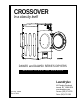
Owners Manual

4 Laundrylux 112999-1
ANTI-WRINKLE
This program selection helps keep permanent press items
wrinkle free when they are not removed from the dryer promptly
at the end of the drying and cooling cycles. The Anti-Wrinkle
program settings are:
1. Guard Delay Time ..............1 to 9 minutes
2. Guard On Time ................... 1 to 99-seconds
3. Active Guard Time..............1 to 99 minutes
FREE DRY MODE
In this program selection, the dryer can be started without the
insertion of coins by simply pressing any one of the three
temperature selections. When set in the “Free Dry” Mode,
the Phase 5 coin microprocessor controller (computer) can
also be programmed to run with an Automatic Cycle (percent
of dryness) or with a Timed Cycle. If the “Free Dry” program
is utilized, the computer ’s L.E.D. display will cycle back and
forth between “FILL” to “FrEE,” unless otherwise programmed.
L.E.D. FLASH DISPLAY
Programmable to allow the L.E.D. readout to display a choice
of “FILL” (no cycle in progress), “Amount To Start” (i.e., 25¢),
or, in the case of free dry, “FrEE.” This program selection also
allows the L.E.D. display to flash back and forth every
2-seconds from “FILL” to “Amount To Start” or, in the case of
free dry, from “FILL” to “FrEE.”
AUDIBLE TONE
In this program selection, a tone (buzzer) will sound for each
coin inserted, program entry, or at the drying and cooling cycles
for a period of 5-seconds to indicate that the cycle is complete.
Additionally, when in the Anti-Wrinkle program, the tone
(buzzer) will sound for 5-seconds at the end of the “Guard On
Time.”
TEMPERATURE DISPLAY
This program selection enables the temperature in the dryer
to be viewed (°F or °C) either while the dryer is off or running.
This service feature shows that the dryer is maint aining the
selected temperature.
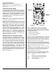
DIAGNOSTICS
All major circuits, including door, microprocessor temperature
sensor, heat, and motor circuit s are monitored. There are
also indicators installed on the outputs of each relay to easily
identify failures, and the door switch has an indicator installed
on the Phase 5 microprocessor controller (computer) to help
indicate failure.
AUTOMATIC DRY TIME
This program selection allows the dryer to run up to a specific
time. During the “AUtO” mode or “FrEE” dry mode this program
is only designed to limit the dryer’s operation during the drying
cycle.
ROTATIONAL SAFE GUARD (Optional)
This program monitors the rotation of the tumbler. If the tumbler
is not rot ating, the Phase 5 coin microprocessor controller
(computer) will disable all output s, an audible tone (buzzer)
will sound, and an error message will be displayed. This
program selection can be programmed to be in the inactive
mode.
BATTERY BACKUP (Optional)
This feature allows the Phase 5 coin microprocessor controller
(computer) to maintain its operating status should a momentary
power interruption occur while the dryer cycle is in progress.
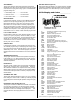
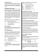
L.E.D. Display and Codes _____________
A Automatic Cycle (Slope Program Factor)
ACOn Accumulative Coin
Adrt Maximum Auto Dryness Time
AFAt Amount for Additional Time
AGt Active Anti-Wrinkle Guard Time
AtIn Accumulative Time
AtSt Amount To Start
AUtO Automatic Mode (Patent No. 4,827,627)
b Automatic Cycle (Heat Loss [of fset] Factor)
bCLO Bad Coin Lockout
bCrS Bad Coin Reset
bUZ Buzzer (Tone)
°CEL Degree in Celsius
CLCC Clear Left Coin Count
Coin Coin Mode
CrCC Clear Right Coin Count
donE Drying and Cooling Cycles Complete
or
Dryer is in Anti-Wrinkle Cycle
door Door Circuit is Open*
dSFL Dryer Sensor Circuit Failure*
°FAr Degree in Fahrenheit
FILL No Cycle in Progress
FLS Flash Display Active
FrEE Free Dry Mode
GdLY Anti-Wrinkle Delay Time
Gont Anti-Wrinkle On Time
Grd Anti-Wrinkle Program Active
HICd High Cool Down
Hot Overheating Condition*
LCC Left Coin Count
LCdE Left Coin Denomination
LOCd Low Cool Down
nbUZ No Buzzer (Tone)
nFLS No Flash Display
nGrd No Anti-Wrinkle
nSEn No Rotational Sensor Selected
PdrY Percent Dry
PL Program Location
PLOC Program Location Automation Review
PPCd Permanent Press Cool Down
PP°F Permanent Press
PUSH Amount to start has been Inserted
Make Temperature Selection
rCC Right Coin Count
rCdE Right Coin Denomination
SEFL Rotational Sensor Circuit Failure*
SEn Rotational Sensor Selected
tFAS Time For Amount to Start
tInE Timed Mode
* Refer to Phase 5 Coin System Diagnostics on page 36 for detailed information.