
User manual


0$,17(1$1&($1'6(59,&,1*
*(1(5$/
$ 5(029$/2)'(%5,6256227'(326,76
Allow the appliance to cool sufficiently before removing all of the coals and firebed components for cleaning
purposes. Once all the ceramics are removed from the firebed check that no debris is located in the burner slots (both
front and rear). If any debris is present it may easily be removed by using a small piece of thin cardboard to ease out
any foreign matter. Be sure to remove the cardboard after use. Any sooty deposits or debris left on the coals may be
removed by using a soft brush or by careful use of a vacuum cleaner. Any sooty deposit on the thermocouple probe
can be cleaned off using a non-fluffy cloth. DO NOT USE ABRASIVE MATERIALS
% 6(59,&,1*&20321(176%(/2:7+(%851(5$66(0%/<
TURN OFF THE GAS SUPPLY TO THE APPLIANCE. Remove coals, coal supports, burner inserts and front
simulated coal. To gain access to components below the burner assembly it has to be removed from the vent box case
by disconnecting the gas supply at the inlet elbow and unscrewing the two screws at the base of the facia panel. Where
the supply is fed from the right hand side across the front of the fire it will be necessary to disconnect the supply from
the isolation tap/elbow.
I. TO CLEAN OR REPLACE THE INJECTOR: Unscrew the compression nut connecting the gas supply to the
elbow injector while supporting the injector. This is to prevent distortion of the framework, unscrew and
remove the gas supply tube from the gas control valve, hold the injector lock nut with a spanner and rotate the
injector. Replace in reverse order.
II. TO REPLACE THE GAS CONTROL (Tap/FSD): Disconnect the three gas pipes and the thermocouple from
the control. Pull off the knob and lay to one side. Undo the retaining nut at the front of the tap niting assembly
to withdraw control from the mounting bracket. Replace in reverse order.
III. TO REPLACE THE PIEZO IGNITER: Pull off the HT lead from the rear of the igniter, prevent the metal
fixing nut from turning, rotate the body of the igniter to unscrew and withdraw the igniter from the front.
Replace in reverse order and reconnect the HT lead.
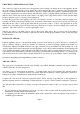
IV. TO REPLACE THE OXY-PILOT ASSEMBLY: The operation of the oxy-pilot depends on the proximity of
the spark electrode and the thermocouple tip, if either of these components are defective the assembly must be
replaced. This is achieved by removing the tube nut from the base of the pilot and the thermocouple from the
FSD also the igniter lead and the two M4 screws securing the bracket to the framework. Replace in reverse
order, the spark gap is shown in Fig 18.
V. TO REPLACE THE FILTER ASSEMBLY: Unscrew and remove the tube nut and tube at the base of the oxy-
pilot assembly, the filter is located in the bottom of the assembly. Replace in reverse order, see Fig 18.
Page 9