
Installation Manual
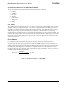
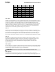
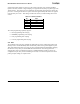
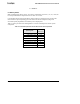
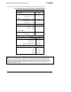
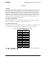
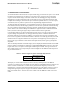
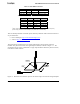


Table Of Contents
- About This Document
- 1 Introduction
- 2 Quick Start for the OEM Kit Users
- 3 Product Overview
- 4 IRIS OEM Reference Board
- 5 Power
- 6 Radios
- 7 Antennas
- 8 Flash Data Logger and Serial ID Chip
- 9 Atmega1281 Fuses
- 10 Sensor Boards & Expansion Connectors
- 11 USB Programming Pod
- 12 Appendix A. Warranty and Support Information

IRIS OEM Edition Hardware Reference Manual
Table 7-2. Hirose MMCX connectors
Type Coax Digi-Key PN Hirose PN
Straight Plug RG178/U H3224-ND MMCX-J-178B/U
Right Angle RG178/U H3221-ND MMCX-LP-178B/U
Right Angle RG316/U H3222-ND MMCX-LP-316/U
Table 7-3. Johnson Components’ MMCX mating connectors*
Type Coax Digi-Key PN Johnson PN
Straight Plug RG178/U J589-ND 135-3402-001
Straight Plug RG316/U J590-ND 135-3403-001
Right Angle RG178/U J593-ND 135-3402-101
Right Angle RG316/U J594-ND 135-3403-101
Right Angle RG 316 DS J595-ND 135-3404-101
*
These connectors require the following hand crimp and die set (Digi-Key part # / Johnson part #):
a) Hand crimp (J572-ND / 140-0000-952), b) Die (JD604-ND / 140-0000-953).
There are literally hundreds of antenna options offered by different vendors and some references
are provided below:
•
Linx Technologies: http://www.linxtechnologies.com/
•
Nearson: http://www.nearson.com/
These antennas are terminated in a coax pigtail, and must have an appropriate connector
installed. They also function best with a ground plane installed, as shown in Figure 7-1. . The
ground plane can be a layer of aluminum or copper tape attached to the lid of a plastic enclosure,
or the lid of a metal enclosure.
1/2 WAVELENGTH
RECOMMENDED
METALLIC
GROUND
PLANE
NUT MAKES
CONTACT WITH
GROUND PLANE
1/2 WAVELENGTH
RECOMMENDED
1/2 WAVELENGTH
RECOMMENDED
METALLIC
GROUND
PLANE
NUT MAKES
CONTACT WITH
GROUND PLANE
Figure 7-1. Illustration of an antenna option for the motes using a Linx antenna and ground plane
Page 2 30-0549-01 Rev. B 6 Doc. # 74