
User Manual


MPR/MIB User’s Manual
Page 48 Doc. # 7430-0021-07 Rev. B
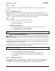
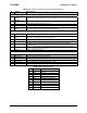
Table 16-2. Pin Outs for a LAN Connection
Pin No. Strand Color Name
1 White and orange TX+
2 Orange TX-
3 White and green RX+
4 Blue 0V POE
5 White and blue 0V POE
6 Green RX-
7 Brown and white -48V POE
8 Brown -48V POE
16.3 Host Software
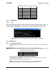
16.3.1 UISP
UISP version 20030820tinyos or newer is required. This version is included in the TinyOS 1.1.0
September 2003 release package. Verify your system is using a compatible UISP version by
entering
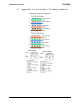
uisp -–version in a Cygwin window (see the example below in Figure 16-3).
Figure 16-3. Screen shot of the output after typing in uisp --version.
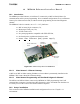
16.4 MIB600 Use
16.4.1 Controls and Indicators
Power. MIB600 power (and power to attached mote) is controlled by the switch labeled
“SW2.”
0 WARNING! Always turn-off the MIB600’s power before installing/removing a mote.
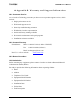
Table 16-4. SW2 Switch Settings.
Position Function
5V External 5V DC power supply selected
POE Power Over Ethernet supply selected
When valid power is detected, the green LED at D5 is ON.
LAN Activity Indicators (RJ45). Green indicates a network connection is present. Yellow
indicates Active ISP serial port traffic is present.
RESET. Pressing the RESET pushbutton (SW1) causes the MIB600 and any
installed/attached MOTE to reset. Note the Serial Server is NOT reset.