
User Manual


MPR/MIB User’s Manual
Page 20 Doc. # 7430-0021-07 Rev. B
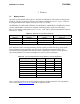
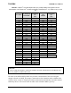
Table 7-3. Estimate of battery life operation for a Mote.
SYSTEM SPECIFICATIONS
Currents
Processor
Example Duty
Cycle
Current (full operation) 8
mA
1
Current sleep 8
µA
99
Radio
Current in receive 8 mA 0.75
Current transmit 12 mA 0.25
Current sleep 2
µA
99
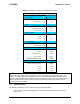
Logger Memory
Write 15 mA 0
Read 4 mA 0
Sleep 2
µA
100
Sensor Board
Current (full operation) 5 mA 1
Current sleep 5
µA
99
Computed mA-hr used each hour
Processo
r
0.0879
Radio 0.0920
Logger Memory 0.0020
Sensor Board 0.0550
Total current (mA-hr) used
0.2369
Computed battery life vs. battery size
Battery Capacity (mA-hr)
Battery Life
(months)
250 1.45
1000 5.78
3000 17.35
; NOTE: In most Mote applications, the processor and radio run for a brief period of time, followed by a
sleep cycle. During sleep, current consumption is in the micro-amps as opposed to milli-amps. This
results in very low-current draw the majority of the time, and short duration spikes while processing,
receiving, and transmitting data. This method extends battery life; however, due to the current surges, it
reduces specified battery capacity. Battery capacity is typically specified by the manufacturer for a
constant nominal current drawn.
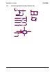
7.2 External Power
The MICA2 and MICAz can be externally powered through either:
1.
The 51-pin connector will supply power and ground to the unit. Refer to connector
description.