
Instruction manual


1.2 Technical Characteristics
3016-2124- Manual_Rev.0 Page 4 8/02/12
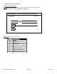
Channel
Characteristics
S
y
nthesizer
Characteristics
< -50 dBC for two carriers each at -5 dBm out
Intermod
±3.0 dB, 21-24 GHz; ±1.5 dB, an
y
1 GHz band; ± 1.0 dB, 36 MHz BW Fre
q
uenc
y
Res
p
onse
<-50 dBc, in band S
p
urious Res
p
onse
125 kHz minimum,
(
1 kHz O
p
t -X1008
)
Fre
q
uenc
y
Ste
p
Invertin
g
or Non-invertin
g
(
user selectable
)
Fre
q
uenc
y
Sense
0.02 ns/MHz2
p
arabolic
;
0.05ns/MHz linear
;
1 ns ri
pp
le
,
36 MHz BW Grou
p
Dela
y,
max.
3 dBm ± 3 dB 10 MHz In/Out Level
± 0.01
pp
m max. over tem
p
internal ref.
;
ext. ref. in
p
ut Fre
q
uenc
y
Accurac
y
> 50 dB, min. Ima
g
e Re
j
ection
30 to +30.0 dB Max./ 0.0 to +30.0 dB ran
g
e
,
1 dB ± 1 dB ste
p
s Gain Max./Ran
g
e
(
ad
j
ustable
)
Other
100-24 ±10% VAC
,
47-63 Hz
,
60 watts max. Power
19 inch
,
1RU Standard Chassis 1.75” hi
g
h X 18.0” dee
p
Size
DB9
(
female
)
- NO or NC contact closure on Alarm Alarm / Remote Connector
BNC
(
female
)
50Ω
,
works for 50 or 75 ohms 10MHz Connectors
2.92 mm
(
female
),
BNC
,
75Ω
(
female
),
(
50Ω IF O
p
t - S29
)
RF
,
IF
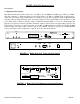
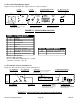
100 90 80 70 60
1MHz 100kHz 10kHz 1kHz 100 MHz
dBC/Hz
Phase Noise @ Frequency
Controls, Indicators
RS232C, 9600 baud
(
RS422/485/o
p
t. -Q, Ethernet/o
p
t -W8, -W18, -W28 Remote
Direct readout LCD; manual or remote selection Fre
q
uenc
y
/Gain Selection
Green LED
;
Red LED
,
Yellow LED Power
,
Alarm
,
Remote
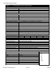
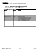
TABLE 1.1 3016-2124 Downconverter Specifications*
20 dB
(
max.
g
ain
)
Noise Fi
g
ure
,
max.
-50 to -30 dBm In
p
ut Level Ran
g
e
21 to 24 GHz Fre
q
uenc
y
+10 dBm Out
p
ut 1 dB Com
p
ression
-20 to 0 dBm Out
p
ut Level Ran
g
e
Out
p
ut
Characteristics
(
IF
)
In
p
ut
Characteristics
(
RF
)
70 ± 18 MHz Frequenc
y
50Ω / 18 dB
(
50Ω
,
works for 50 or 75 ohms
)
Im
p
edance / Return Loss
50Ω /18 dB t
yp
.
,
14 dB min. Im
p
edance / Return Loss
RF Mon.
,
-3 ±3 dB
,
50 ohm - W73
IF Mon.
,
-20dB
,
50 ohm - W71
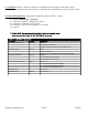
Available
O
p
tions
Test Data - W16
1 KHz Ste
p
s
Ethernet with TCP/IP
,
Telenet
Ethernet with Web Browser & SNMP
Ethernet with Web Browser
(
WB
)
See Table 2.2 - PG 9 Connector / Im
p
edance
- X1008
- W28
- W18
- W8
RS485 Remote Interface -
Q
*+0 to +50 degrees C; Specifications subject to change without notice.
-01
S29
W8
W16
W70
X1008
Bundled
O
p
tions