
Instruction manual

Model 2416-x02
Multi Channel Downconverter
2416-402 Four Channel • 2416-302 Three Channel • 2416-202 Two Channel • 2416-102 One Channel
1.0 General
1.1 Equipment Description
The 2416-402 Downconverter has four individual channels, each one converts 950 to 2150 MHz to 70 MHz in
125 kHz steps using PLL in “fractional frequency mode”(NOTE 1) with low group delay and flat frequency
response. Synthesized local oscillators (LO) (NOTE 1) provide frequency selection. Multi-function push button
switches select the input frequency, gain, and other parameters. Front panel LEDs provide indication of DC
power, PLL alarm or Remote operation. Gain is adjustable manually over a 0 to +30 dB range. The frequency
and gain of each channel are also remotely selectable. Parameter selection and frequency and gain settings
appear on the LCD display. Connectors are Type F female for the RF, and BNC female for the IF and external
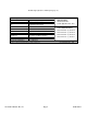
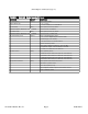
10 MHz reference input and output. The table below shows available options. LNB +24 VDC (option L1, on
channel 1 only) and 10 MHz reference can be inserted on the RF lines. The 2416-402 is powered by a 100-240
±10% VAC, 47-63 Hz power supply, and is contained in a 1 3/4” X 19” X 16” rack mount chassis.
* 2416-x02, Four (4) Channels, 2416-302, Three (3) Channels, 2416-202, Two (2) Channels, 2416-102, One (1) Channel.
MENU
EXECUTE
MODEL 2416
CROSS TECHNOLOGIES INC.
DOWNCONVERTER
REMOTE
POWER
ALARMS
1674.125 1926.250
1926.375 2086.625
------ CH 1 -------- ------ CH 2 --------
1234
------ CH 3 -------- ------ CH 4 --------
A
B
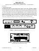
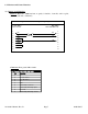
FRONT PANEL (2416-402 - Four Channel show)
PSA
GND
J11 J12
AND
MONITOR
CONTROL
CHANNEL 4
RF IN
J10
VDC
ON
RF
J9
RF OUT
CHANNEL 3
RF IN
J8
VDC
ON
RF
J7
RF OUT
CHANNEL 1
RF IN
J2
VDC
ON
RF
J1
RF OUT 10 MHZ REF
OUTPUT
10 MHZ IN/OUT
J4
J3
10 MHZ REF
INPUT
CHANNEL 2
RF IN
J6
VDC
ON
RF
J5
RF OUT
PSB
1
5
234
6789
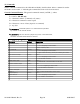
REAR PANEL (2416-402 - Four Channel show with optional Ethernet)
FIGURE 1.1 Model 2416-x02 Front and Rear Panels
SW,PLL,ATT,
10M CONTROL
M&C
CONTROLLER
EXT
10MHz
INT 10MHz
10MHz
TO
VCOs
2416-x02
Block
Diagram
0.95 to 2.15 BP 2400 MHz BP
3.35 to
4.55 GHz
var
atten
70
MHz
OUT
2470
MHz
200 MHz LP
0.95
to
2.15
GHz
IN
SAME FOR FREQUENCY CHANNEL 2
SAME FOR FREQUENCY CHANNEL 3
SAME FOR FREQUENCY CHANNEL 4
------ CH 1 -------- ------ CH 2 --------
------ CH 3 -------- ------ CH 4 --------
1674.125 1926.250
1926.375 2086.625
10 MHz, std.,
DC - O
p
t L4
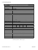
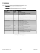
FIGURE 1.2 Model 2416-x02 Downconverter Block Diagram
(Block Diagram applies to Models 2416-102, 202, 302 & 402)
2416-402 Manual, Rev. D Page 3 04/01/2015