
Instruction manual
2017-14 Manual, Rev. 0 Page 4 01/31/13
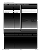
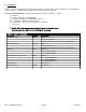
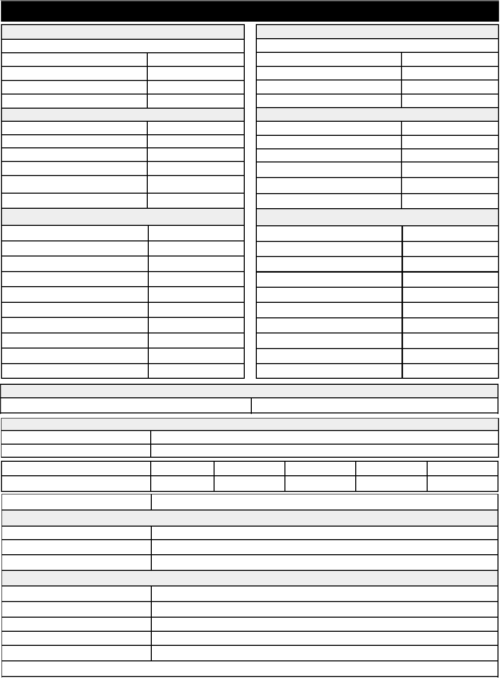
1.2 Technical Characteristics
S
y
nthesizer
Characteristics
NONE
,
Fixed Fre
q
uenc
y
Fre
q
uenc
y
Ste
p
± 1.0
pp
m internal reference
(
±0.01
pp
m, O
p
tion -H
)
Fre
q
uenc
y
Accurac
y
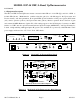
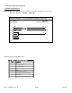
-110 -100 -85 -80 -75
1MHz 100kHz 10kHz 1kHz 100 MHz
dBC/Hz
Phase Noise @ Frequency
*+10˚C to +40˚C; Specifications subject to change without notice. © 2013 Cross Technologies, Inc.
100-240 ± 10% VAC
,
47-63 Hz
,
45 watts maximum Power
BNC
(
female
),
50Ω/75Ω 10 MHz Connectors
T
yp
e F
(
female
)
/ BNC
(
female
)
RF/IF
(
UHF
)
Connector
Other
RS232C
,
9600 baud
;
(
RS485
,
O
p
tion Q
,
Ethernet O
p
tional
)
Remote
Controls
,
Indicators
19 inch
,
1 RU Standard Chassis
,
1.75” hi
g
h X 16.0” dee
p
Size
DB9 - NO or NC contact closure on Alarm Alarm/Remote Connector
Green LED
,
Red LED
,
Yellow LED Power/Alarm/Remote
Direct readout LCD;
p
ushbutton switches or remote selection Gain Selection
3 dBm ± 3 dB, 75 ohms
(
O
p
tion E1
)
10 MHz Level In/Out Level
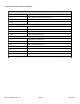
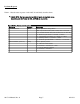
TABLE 1.0 2017-14 UHF, L-Band, Up/Downconverter Specifications*
+10 dBm 1 dB Com
p
, maximum
g
ain
< -60 dBm S
p
urious, in Band, Si
g
nal ind..
< -55 dBC, 0 dBm S
p
urious, in Band, Si
g
nal rel.
Non-invertin
g
Fre
q
uenc
y
Sense
± 0.5 dB Fre
q
uenc
y
Res
p
onse
,
40 MHz
± 2 dB Fre
q
uenc
y
Res
p
onse Band
< -50 dBm Intermod - 2 Carriers
< -55 dBm S
p
urious, Out of Band
< -55 dBC, minimum Ima
g
e Re
j
ection
+30 to 0 dB Gain, Ran
g
e, 0.5dB ste
p
s
> 60 dB Mute @ 0 dBm Out
-20 dBC OUT
(
±3 DB
)
Mon. Level
(
O
p
tion W78
)
20 db @ max.
g
ain Noise Fi
g
ure
,
maximum
+30 ± 3 dB Gain
,
Maximum at Fc
Channel
Characteristics
-15 to 0 dBm Out
p
ut Level Ran
g
e
0.2 to 0.4 GHz Fre
q
uenc
y
Out
p
ut
Characteristics
In
p
ut
Characteristics
(
UHF
,
L
)
1.2 to 1.4 GHz Fre
q
uenc
y
(
GHz
)
50Ω / 14 dB Im
p
edance/Return Loss
-40 to -25 dBm In
p
ut Level Ran
g
e
50Ω / 14 dB Im
p
edance/Return Loss
UPCONVERTER
+10 dBm 1 dB Com
p,
maximum
g
ain
< -60 dBm S
p
urious
,
in Band
,
Si
g
nal ind.
< -50 dBC, 0 dBm S
p
urious, in Band, Si
g
nal rel.
Non-invertin
g
Fre
q
uenc
y
Sense
± 0.5 dB Fre
q
uenc
y
Res
p
onse, 40 MHz
± 2 dB Fre
q
uenc
y
Res
p
onse Band
< -50 dBm Intermod - 2 Carriers
< -45 dBm S
p
urious, Out of Band
> 50 dB, minimum Ima
g
e Re
j
ection
+30 to 0 dB Gain
,
Ran
g
e
,
0.5dB ste
p
s
N/A Mute @ 0 dBm Out
+10 dBm IN
(
±3 DB
)
Mon. Level
(
O
p
tion W78
)
15 @ max.
g
ain Noise Fi
g
ure, maximum
+30 ± 3 dB Gain, Max at Fc
Channel
Characteristics
-20 to 0 dBm Out
p
ut Level Ran
g
e
1.2 to 1.4 GHz Fre
q
uenc
y
Out
p
ut
Characteristics
In
p
ut
Characteristics
(
L
,
UHF
)
0.2 to 0.4 GHz Fre
q
uenc
y
(
GHz
)
50Ω / 14 dB Im
p
edance/Return Loss
-50 to -30 dBm In
p
ut Level Ran
g
e
50Ω / 14 dB Im
p
edance/Return Loss
DOWNCONVERTER
.2 - .4 GHz Out ≥ -40 dBc @ maximum in
p
ut level
Downconverter
2nd
Harm