
Instruction manual
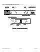
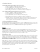
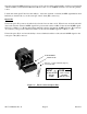
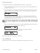
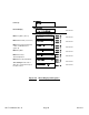
Tables 2.1 & 2.2 shows the input and output connectors on the rear panel.
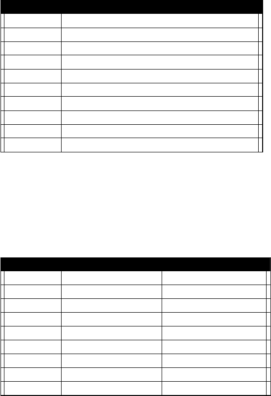
TABLE 2.1 JJ10
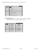
2.1 J10 Pinouts (RS-232C/422/485*)
Pin Function
1 Rx-
2 Rx+ (RS-232C)
3 Tx+ (RS-232C)
4Tx-
5GND
6 Alarm Relay: Common
7 Alarm Relay: Normally Open
8 Not Used
9 Alarm Relay: Normally Closed
*Remote Serial Interface
Interface: DB-9 Male -- Protocol: RS-232C (RS-232C/422/485 option -Q),
9600 baud rate, no parity, 8 data bits, 1 start bit, 1 stop bit.
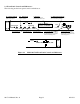
TABLE 2.2
I
IF/RF
2.2 IF/RF Connector Optionns
Options
Option IF RF
STD BNC, 75Ω Type F, 75Ω
-B BNC, 75Ω BNC, 75Ω
-C BNC, 75Ω BNC, 50Ω
-D BNC, 50Ω BNC, 50Ω
-J BNC, 50Ω Type F, 75Ω
-N BNC, 75Ω Type N, 50Ω
-M BNC, 50Ω Type N, 50Ω
-S BNC, 50Ω SMA, 50Ω
2017-14 Manual, Rev. 0 Page 12 01/31/13