
Instruction manual

MODEL 2015-25 Upconverter
1.0 General
1.1 Equipment Description
The 2015-25 Upconverter converts 70 ± 18
MHz to 2000 to 2500 MHz in 1.0 MHz steps (0.5 MHz steps
optional) with low group delay and flat frequency response. Synthesized local oscillators (LO) provide
frequency selection. Multi-function push button switches select the RF frequency, gain, and other parameters.
Front panel LEDs provide indication of DC power (green), PLL alarm (red), Remote operation (yellow) or the
TX carrier is Muted (yellow). Variable attenuators for the IF input and output provide a gain range of -10 to +30
dB as adjusted by the front panel multi-function pushbutton switches. Remote operation allows selection of
frequency and gain. Parameter selection and frequency and gain settings appear on the LCD display.
Connectors are BNC female for IF input, external reference input, and RF output. The 2015-25 is powered by a
100-240 ± 10% VAC power supply, and is housed in a 1 3/4” X 19” X 16” rack mount chassis.
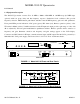
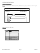
MENU
EXECUTE
MODEL 2015
CROSS TECHNOLOGIES INC.
F=2475 G=+10.0
MUTEREMOTE POWER ALARM
UPCONVERTER
FRONT PANEL
AC
RF OUT
GND
J4 J5J3J18
10 MHZ REF
10 MHZ
IF IN
EXT REF
OUTPUT INPUT
J10
AND
MONITOR
CONTROL
15 234
6789
REAR PANEL
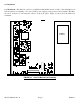
FIGURE 1.1 Model 2015-25 Front and Rear Panels
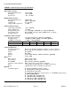
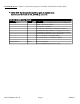
2.0
to
2.5
GHz
OUT
70
MHz
IN
1.0 to 2.8 GHz
BP
CONTROLLER
F=2475 G=+10.0
1750 MHz
BP
1820
MHz
3.8
to
4.3
GHz
var
atten
EXT
10MHz*
*OPTIONAL
var
atten
INT
10MHz
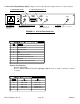
FIGURE 1.2 Model 2015-25 Upconverter Block Diagram
2015-25 Manual, Rev. G Page 3 02/01/11