
Technical Manual

Technical Manual
ARGUS AM Floor System
Cross Point Device Explorer v1.2 Page 46 of 65
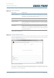
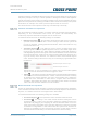
Noise level indicator
The noise level indicator, located on the right of each scope view image, shows a value
between zero and one hundred, which represents the amount of noise that is being
detected. A high noise level will result in reduced detection, which means that specified
detection distances might not be achieved. To improve this situation, the noise source(s)
must be located and removed when possible.
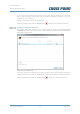
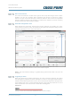
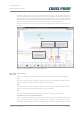
Extended configuration views
When besides the transceiver antenna also receiver antennas are installed, the scope
views of these receivers can also be viewed and the phase and anti-phase settings can be
adjusted individually for each connected antenna.
Figure 45: Scope view of transceiver and receiver antenna signals
NOTE: The Auto threshold setting is a global setting, which means that it is set for all
channels.
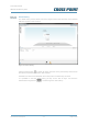
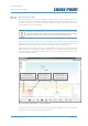
Triggering an alarm
When the signal of tag or label is detected by any of the connected antennas, the control
unit will trigger the tag detected alarm notification. An alarm is only triggered when both the
SIGNAL and PHASE requirements are met. This means that the signal must be higher than
the threshold level and a constant threshold degrees angle has been detected. If one of
these requirements is not met, then the alarm will not be triggered.
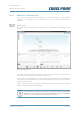
Situation 1
SIGNAL too low and continuous PHASE detected; result: no alarm
Toggle these buttons to view
or hide the associated scope
view(s)