
Technical Manual

Technical Manual
ARGUS AM Floor System
The ARGUS AM Control Unit v1.2 Page 29 of 65
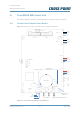
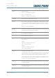
11.2 Control Unit PCB Components
Table 4 shows the Control Unit PCB components and a description of their function.
Component
Function
AI
Connector for the optional external alarm indicator
AL
Connector for the integrated alarm LEDs indicator
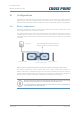
ANT 1
ANT 2
Floor antenna coil TRx1
Floor antenna coil TRx2
BAT
Backup battery for internal clock
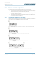
BUS A
Field Bus A connector for RJ45 connection. Allows the board to
be connected in the Field Bus structure.
BUS B
Field Bus B connector for RJ45 connection. Allows the board to
be connected in the Field Bus structure.
BUZZER
On-board buzzer for alarm notifications
BUZZER JUMPER
Jumper to enable / disable the buzzer. Default this jumper must
be placed.
Input 1
Input to manually trigger an alarm using an external push button
LED 1
Error indicator
LED 2
Indicator for development purposes
LED 3
Activity indicator
LED 4
Detection active indicator
Blinking = startup, on = detection active
LED 5
Application active indicator
Slowly blinking = application active