
Technical Manual


Technical Manual
ARGUS AM Floor System
Configurations v1.2 Page 23 of 65
10 Configurations
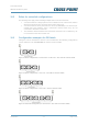
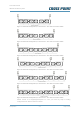
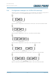
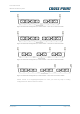
Depending on the width of the entrance that needs to be secured, one or more ARGUS
systems may need to be combined with extra receiver coils. The images below show an
indication of the maximum entrance widths that can be secured with specific configurations.
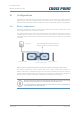
10.1 Basic configuration
The basic configuration consists of one Control Unit and 2 transceiver (TRx) coils. These
2 transceiver coils form 1 transceiver antenna.
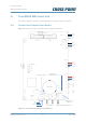
The distance between the 2 TRx coils must be 30cm. The short connector piece, which is
supplied with the antenna coil, must be removed from the antenna and must be used to
create this distance and to interconnect the two TRx coil housings resulting in a more stable
assembly.
Figure 12: Basic configuration with one transceiver antenna (consisting of 2 TRx coils)
The entrance width that can be secured with such a basic configuration depends on
whether DR labels or OSTRA F25 tags are used. When OSTRA F25 tags are used, the
secured entrance width will be more. See the next sections for configuration examples for
different entrance widths, specified for DR labels and OSTRA F25 hard tags.
Always connect two TRx coils and they must be placed next to each using
the short connector piece to interconnect the two TRx coils.
It is not possible to connect only one TRx coil! It is also not possible to
connect only 1 TRx and 1 Rx coil.
30 cm connector piece
Wall / door frame
Wall / door frame
Control Unit
The combination of 2 transceiver coils are
always regarded as 1 transceiver antenna!