
Technical Manual

Technical Manual
ARGUS AM Floor System
Connections v1.2 Page 17 of 65
8 Connections
In the following chapters the connections between the ARGUS AM Control Unit and the
CrossCONNECT Access Point are described.
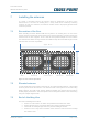
Furthermore the Printed Circuit Board (PCB) of the Control Unit and the manual
adjustments are explained.
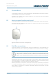
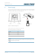
8.1 How to access the electronic board
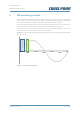
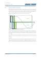
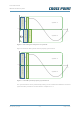
In order to be able to access the electronic board, the control unit lid needs to be removed.
This can be done by untightening two screws; one located at the top and one located at
the bottom of the control unit.
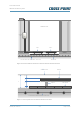
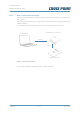
Figure 8: Position of screws for removing the lid
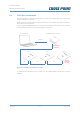
8.2 Field Bus connections
Cross Point devices are interconnected through the Field Bus by using preferably FTP
cables, because FTP has an advantage to eliminate noise because of the extra shielding.
The Cross Point Field Bus requires the devices to be connected in a
“daisy chain” connection. A “star” network is not allowed and will result
in poor or no communication between the devices and the Access Point!
Each ARGUS AM Control Unit is configured with a unique address, which is factory set and
cannot be changed. A PC/laptop enables local maintenance of the Control Unit by using
the CrossCONNECT Access Point and Device Explorer software.
When the Field Bus is connected to the Access Point and the Access Point is connected
to a Local Area Network (LAN), local servicing and data retrieval is possible. When the
Access Point is connected to the internet, subscription based remote service and data
retrieval will be available.