
Specifications
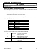


Component Testing Procedures
!
WARNING
To avoid risk of electrical shock, personal injury or death; disconnect power to oven before servicing, unless
testing requires power.
12 16023528 ©2004 Maytag Services
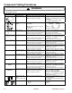
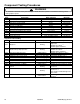
Illustration Component Test Procedure Results
Oven light socket Remove one wire from receptacle and
test resistance of terminals.....................
Measure voltage at oven light.................
Indicates continuity with bulb screwed in.
120 VAC, see wiring diagram for terminal
identification.
If no voltage is present at oven light,
check wiring or light switches.
L2
L1
H2
P
H1
1
2
3
4
5
Push-to-Turn Infinite
Switch
Connect Volt-ohms meter to
H1 and H2.
Measure the following for voltages at
LO, MED, HI:
H1 to H2 ...............................................
Approximate
Time On Time Off
LO 5% 95%
MED (4-5) 35% 65%
HI 100% 0%
240 VAC, if not replace switch.
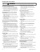
Bake element Measure voltage at bake element...........
Disconnect wire leads to element and
measure resistance of terminals.............
240 VAC, see wiring diagram for terminal
identification. If no voltage is present at
bake element, check wiring.
Approximately 21.7
Ω, if not replace.
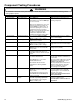
Broil element Measure voltage at broil element............
Disconnect wire leads to element and
measure resistance of terminals.............
240 VAC, see wiring diagram for terminal
identification. If no voltage is present at
broil element, check wiring.
Approximately 18.7
Ω, if not replace.
1250W
Coil element, 3-turn Measure voltage at coil element .............
Disconnect wire leads to element and
measure resistance of terminals.............
240 VAC, see wiring diagram for terminal
identification. If no voltage is present at
element, check wiring.
Approximately 43 to 49
Ω, if not replace.
2100W
Coil element, 4-turn Measure voltage at coil element .............
Disconnect wire leads to element and
measure resistance of terminals.............
240 VAC, see wiring diagram for terminal
identification. If no voltage is present at
element, check wiring.
Approximately 33 to 38
Ω, if not replace.
1500W
Coil element, 4-turn Measure voltage at coil element .............
Disconnect wire leads to element and
measure resistance of terminals.............
240 VAC, see wiring diagram for terminal
identification. If no voltage is present at
element, check wiring.
Approximately 35 to 39
Ω, if not replace.
2350W
Coil element, 5-turn Measure voltage at coil element .............
Disconnect wire leads to element and
measure resistance of terminals.............
240 VAC, see wiring diagram for terminal
identification. If no voltage is present at
element, check wiring.
Approximately 21 to 25
Ω, if not replace.
1200W
Ribbon element, 6" Measure voltage at ribbon element ........
Disconnect wire leads to element and
measure resistance of terminals.............
240 VAC, see wiring diagram for terminal
identification. If no voltage is present at
element, check wiring.
Approximately 43 to 49
Ω, if not replace.
2500W
Ribbon element, 9" Measure voltage at ribbon element ........
Disconnect wire leads to element and
measure resistance of terminals.............
240 VAC, see wiring diagram for terminal
identification. If no voltage is present at
element, check wiring.
Approximately 20 to 24
Ω, if not replace.
1500W Inner
700W Outer
Ceran element, Dual Disconnect wire leads to element and
measure resistance of terminals.............
Measure voltage at element ...................
Inner – 36 – 40
Ω, if not replace.
Outer – 76 – 84
Ω, if not replace.
240 VAC, see wiring diagram for terminal
identification. If no voltage is present at
element, check wiring.
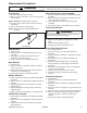
Oven indicator light
and
Surface indicator light
Measure voltage at indicator light........... If voltage is present and light does not
work, replace light.
If no voltage is present at indicator light
check wiring.
Rocker switch Measure continuity of switch positions:
Closed ................................................
Open...................................................
Continuity
Infinite