
Specifications


8
3.2 JUMPER SETTINGS AND WIRING EXAMPLES, CONT’D…..
System wiring can originate at the “CAN-IN” or “CAN-OUT” wiring terminals of the PDC. They are parallel connected internally. System wiring
can also originate at both and run in two directions to save on conduit and wire.
Several installation examples are described below with correct jumper positions indicated. See the page-12 for diagram layouts to match the
examples described below.
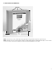
Example-1: One run of system wiring at or under 2000’ from the PDC controller out to a number of DST transmitters with no CNB bridges
required and no remote power supply required. One jumper is placed at “J5” jumper pin location for (“IN”) or (“OUT”) inside the PDC controller,
depending on which wiring terminal strip is utilized. The “IN” or “OUT” terminals can be used for system wiring. They are paralleled inside the
circuit. One jumper is placed at the “J2” jumper pin location inside the DST transmitter located at the end of the system wiring run.
PDC
DST DST DST
DST DST DST
J5
END-OF LINE
JUMPER
JUMPER
Installation Example-2:
PDC
DST DST CNB-1
DST DST DST
J5
END-OF LINE
JUMPER
JUMPER
DST
JUMPERS
PDC
DST
J5
DST DST
DST
DST
DST
DST
DST
END-OF LINE
JUMPER
END-OF LINE
JUMPER
Installation Example-3:
“NO”
JUMPERS
HERE
PDC
DST
J5
DST DST
DST
CNB-1
DST
DST
JUMPERS
END-OF LINE
JUMPER
END-OF LINE
JUMPER
CNB-2
JUMPERS
Installation Example-4:
“NO”
JUMPERS
HERE
CNB-3
JUMPER
DST DST DST
DST
END-OF LINE
JUMPER
NODE-1
Installation Example-1: