
Specifications


7
3.1 WIRING
Digital System: If a digital system has been selected, refer to “WIRING SPECIFICATIONS AND INSTALLATION INSTRUCTIONS” on page 5.
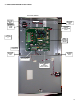
The wiring terminal strip for the digital system can be found at the bottom middle edge of the circuit board. Refer to section 4.1, page-10 for a
detailed wiring drawing.
NOTE-1: Do not use solid-core wire at circuit board terminals. Solid-core wire has memory and can tear a soldered terminal right off the circuit
board. This is not covered under warranty.
NOTE-2: Common, accepted wire colors for positive, negative and signal VDC wires are: Red for positive, Black for negative and White or
Yellow for signal.
NOTE-3: 14 gauge wire should be utilized for longer wire runs to minimize voltage drop.
NOTE-4: All wiring must be “daisy-chain” installed. All four wires must go to the input terminal of a digital transmitter or CAN network bridge
and must exit the output terminal strip to go onto the next transmitter or CAN network bridge.
NOTE-5: It is imperative that a termination jumper is placed on the last transmitter on the wiring run (end-of-line). The jumper termi-
nates the resistor installed on the DST circuit board. The resistor installed on the PDC circuit board provides termination at the beginning of the
wiring run. A jumper termination is also required for any CAN network bridges installed. Consult “JUMPER SETTINGS AND WIRING EXAM-
PLES” below.
Relay Wiring: Both analog and digital systems are supplied with dry contact relays for control of remote devices such as exhaust fan and make
up air fan contactors, etc. The relay wiring terminal strips are located along the right side (line voltage side) of the circuit board. Take note of
the maximum relay specifications as listed in section 2.0 when connecting load devices. With regards to fans, relays should be used to control
fan starters or contactors and NOT the fan motor directly. If device to be controlled is a higher voltage or current than the system relays are
capable of handling, use a heavier rated, external dry contact relay to handle the heavier load and use the relay contacts inside the PDC to
activate the coil on the external relay.
NOTE: STAR-WIRING CONFIGURATIONS CANNOT BE USED ON THIS SYSTEM. PROBLEMS ARISING FROM USING SUCH A WIRING
CONFIGURATION ARE NOT THE RESPONSIBILOITY OF CETCI.
3.2 JUMPER SETTINGS AND WIRING EXAMPLES
The PDC circuit design is such that the relay coils can be selected as “normally energized” or “normally de-energized”. Unless advised, the
factory default is “normally energized” in non gas alarm condition. Thus, control wiring should be connected to “COM” and “N/C”. In the event
of a hardware, wiring or sensor failure (solid-state sensor only), the relay coil changes state and the device being controlled operates
continuously until the fault condition is corrected. Consult the programming sheet supplied with the controller for the factory program that was
set up.
Example-2: One run of system wiring at approximately 1800’ from the PDC controller out to a number of DST transmitters with one CNB
network bridge installed at the 2000’ point along the BUS wiring. One jumper is placed at “J5” jumper pin location for (“IN”) or (“OUT”) inside
the PDC controller, depending on which wiring terminal strip is utilized. The “IN” or the “OUT” can be used for the system wiring. They are
paralleled inside the circuit. One jumper is placed at the “J2” jumper pin location and one jumper is placed at the “J3” jumper pin location inside
the CNB bridge. One jumper is placed at the “J2” jumper pin location inside the DST transmitter located at the end of the system wiring run.
Example-3: Two runs of system wiring, one from the “IN” and one from the “OUT” wiring terminals inside the PDC. Each wiring run is 1000’
long. No jumper is to be used at the “J5” jumper pin location inside the PDC. One jumper is placed at the “J2” jumper pin location inside the
DST transmitter located at the end of each of the system wiring runs.
Example-4: Two runs of system wiring, one from the “IN” and one from the “OUT” wiring terminals inside the PDC. Each wiring run is 1000’
long. Two CNB bridges are required. No jumper is to be used at the “J5” jumper pin location inside the PDC. One jumper is placed at the “J2”
jumper pin location inside the CNB bridge and One jumper is placed at the “J3” jumper pin location inside the CNB bridge. One jumper is
placed at the “J2” jumper pin location inside the DST transmitter located at the end of each system wiring run.
The “T” drop can be achieved but requires a CNB bridge for every “T” drop. One jumper is placed at the “J3” jumper pin location only inside the
CNB bridge. One jumper is placed at the “J2” jumper pin location inside the DST transmitter located at the end of the system wiring run.
NOTE: “T” DROPS ARE NOT RECOMMENDED FOR PDC SYSTEM WIRING.
Termination jumpers are required in various areas to ensure communication is established between the PDC controller and the various
transmitters and peripheral devices.