
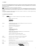
Specifications


6
3.0 INSTALLATION
Standard: Four 3/16” diameter mounting holes can be located at the corners inside the enclosure base. Take caution when using installing
tools inside system enclosure to avoid damaging internal components.
Water/dust tight: These enclosures are optional and are supplied with four mounting feet that must be attached by the installer. A liquid tight
conduit fitting must be used to maintain the water tight state of this enclosure.
Security: PDC should be installed inside a locked electrical, mechanical or instrumentation room. In the event that it is installed in a less secure
area, the enclosure has a key locking, hinged door.
NOTE-1: Care should be taken to avoid installing controllers in areas that present a lot of potential for EMI (electromagnetic interference) and
RFI (radio frequency interference). The system metal enclosure will provide a certain amount of RFI protection. Damage to controller circuitry
from over exposure to large amounts of EMI and RFI are not covered under warranty.
NOTE-2: The PDC controller is available configured for either eight analog inputs, or sixteen, thirty-two, sixty-four, ninety-six or one hundred
and twenty-eight digital inputs. PDC circuit boards can be supplied for analog transmitters or for digital transmitters or for both. The digital
output terminal strip is required if the PDC is to communicate to a remote annunciator panel.
NOTE-3: The preferred installation involves installing the transmitter with the lowest ID code number representing channel-1 on the controller,
the next consecutive ID code number representing channel-2 on the controller and so on. THIS IS HOW THE CONTROLLER IS ALWAYS
PROGRAMMED AT THE FACTORY. ID addresses 1 to 8 are reserved for analog transmitters. ID addresses 9 to 128 are reserved for
digital transmitters.
Sensor Head Mounting Heights
Carbon Monoxide: 4’ to 6’ from the floor
Nitrogen Dioxide: 4’ to 6’ from the floor (garage applications)
Propane: 6” from the floor
Methane / Hydrogen: On or near the ceiling
Refrigerants (Freons): 6” from the floor or near the most probable leak source
Ammonia: On or near the ceiling
Chlorine: 6” from the floor
Ozone: 6” to 24” from the floor
Oxygen: 4’ to 6’ from the floor
Hydrogen Sulphide: 3” to 5” from the floor
Sulphur Dioxide: 6” from the floor
Nitric Oxide: 4’ to 6’ from the floor
Ethylene Oxide: 6” to 12” from the floor (application dependent)
Environment
If sensor heads or controller are to be installed in a wet environment optional water/dust tight, corrosion resistant enclosures are available. If
sensor may be subject to splashed liquid, optional splash guards are available. TO MAINTAIN WATER/DUST TIGHT RATING OF EN-
CLOSURES, LIQUID TIGHT CONDUIT FITTINGS MUST BE UTILIZED. FOLLOW INSTALLATION INSTRUCTIONS CAREFULLY. COR-
ROSION DAMAGE FROM IMPROPERLY INSTALLED ENCLOSURES IS NOT COVERED UNDER WARRANTY.
3.1 WIRING
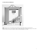
Line Voltage Power to System: Three knock-outs have been provided along the top edge and three along the bottom edge of the enclosure
base for conduit and wire entry. Take caution when “punching” out metal knockouts and installing conduit connections to avoid damaging
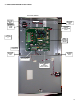
internal system components. The interior of the PDC is divided into two general sections with regards to voltages. The “line voltage section”
is located at the top right corner and right hand side of the enclosure interior. The “low voltage section” is located across the bottom and up the
left side of the system enclosure.
A large terminal strip and ground studs have been provided, at the top right corner of system enclosure interior, to secure line power and
ground wires. Take note of power requirements as listed in “CONTROLLER SPECIFICATIONS” on page-4.
Low Voltage Power to Sensor / Transmitters:
Analog System: If an analog system has been selected, wiring should consist of 2-conductor 14-16 gauge wire for 24V nominal supply to
remote sensor / transmitters. If wiring runs are more than 2000’, use 14 gauge stranded wire. The 24V supply can be daisy-chained to the
remote sensors. The wiring terminal strip for the 24V supply can be found at the bottom left edge (low voltage section) of the circuit board. The
analog signal loop consists of one signal wire for each sensor. These wires can usually be 16 to 18 gauge. Signal wires should be shielded if
they are not to be run within conduit. The wiring terminal strip for the signal wires can be found at the left lower side (low voltage section) of the
circuit board. Refer to section 4.3, page-12 for a detailed wiring drawing.