
Specifications


5
2.0 CONTROLLER SPECIFICATIONS, CONT’D…..
Fuses: Replaceable: Primary: 1.5 amp, Power supply: 2.0 amp
Options: a) BACnet Output Module
b)Remote mounted 4” diameter strobe light
c) Remote mounted combination strobe light/siren alarm
d) Remote mounted 5” industrial horn (115VAC)
e) Water/dust tight, corrosion resistant system enclosure
f) Remote relay module
g) Remote analog output module
h) Remote annunciator (remote display)
i) Remote power supply
2.1 WIRING SPECIFICATIONS & INSTALLATION INSTRUCTIONS
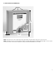
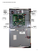
PDC controller: should be installed in a locked electrical room to prevent vandalism. There are three knockouts located along the top
edge and three along the bottom edge of the control enclosure for conduit entry. Use caution when punching out knock outs to avoid contact
and damage to circuit boards.
Wiring specifications: are critical to the proper operation of a digital system. The wiring consists of a 2-conductor, 14 gauge, stranded
wire for 24V power and COM plus 2-conductor, 18 gauge, shielded, low capacitance, “twisted-pair” for communications (Data-A and Data-B).
All wiring must be installed in conduit according to local electrical codes. System problems arising from the installation and/or use of wire or
cable not specified herein are not covered under warranty.
Wiring connections: for the DST transmitters and CAN Network bridges must be “ daisy-chained”. This means four wires going into the
device and connected to the “IN” side of the wiring terminal strip and four wires connected to the “OUT” side of the wiring terminal strip and
going out of the device and on to the next device. This is the only acceptable method of termination. Double check to ensure the data-A and
data-B lines of the BUS wiring are not crossed from transmitter to transmitter.
Wiring shield: from the 2-conductor, shielded, twisted-pair portion of the wiring must be connected to the PDC negative connection located
at the bottom right corner of the PDC board “BATT BACK-UP” terminal strip. At each DST or CAN, the shields must be connected together
but not to common or ground. Installed correctly, this creates a continuous shield from the PDC to the last transmitter on the wiring run. At
the last DST transmitter on the wiring run, the shield must be left floating. It is grounded at one point only and that is the PDC controller.
DST digital transmitters: DST transmitters are digital gas transmitters with built-in sensors for various gases. Carbon Monoxide (CO)
sensor versions should be installed at 4’ to 6’ from the floor. The DST digital transmitters with Propane (C3H8) sensors should be installed at
6” from the floor. The DST digital transmitters with Nitrogen Dioxide (NO2) sensors should be installed at 4’ to 6’ from the floor. Con-
sult the manual for mounting heights for other gas sensor types. Conduit can enter the DST enclosures from the back of the base or from the
top or bottom of the base. Take care when installing conduit to avoid damaging the electronic circuits. Problems arising from damage to circuit
board during installation are not covered under warranty.
CAN Network bridges: CAN network bridges act as “repeaters” for the data communications by reassembling the data (correcting
any potential corruption that may have occurred in the data along the wiring run) and sending it on to the DST or PDC. They MUST be in-
stalled every 1000’ of wire (cable). If the distance is longer than 2000’ communication problems could occur. The installer must also consider
any loops and corners in calculating this distance for a total of no more than 2000’. Conduit can enter the CAN enclosures from the back of the
base or from the top or bottom of the base. Take care when installing conduit to avoid damaging the electronic circuits. Problems arising from
damage to circuit board during installation are not covered under warranty.
Remote power supplies: Remote power supplies are used to “ boost” the 24VDC power wiring to compensate for voltage drops cre-
ated by extra resistance from long wiring runs. It is critical that the DST transmitters receive at least 20 to 24 VDC. The power supply MUST be
installed at approximately 2/3 of the way along any one wiring run. Example: If a specific wiring run from the PDC controller is 2500’ to the
last DST, the power supply must be installed at approximately the 1600’ area. The power supply “boosts” the voltage to transmitters “down
line” from it as well as increasing voltage to the “up line” transmitters closest to it.
NOTE: The remote power supply requires 120VAC line voltage power. The output from this power supply is a regulated 24VDC and it
MUST be parallel connected, at a DST transmitter, to the 24VDC supply wires coming from the PDC controller. This means the posi-
tive output of the remote power supply must be connected to the positive 24V line of the BUS wiring and the negative output of the remote
power supply must be connected to the “COM” line of the BUS wiring.
Jumpers: must be placed on the correct terminals of the PDC controller as well as the last (end-of-line termination) DST transmitter on
any wiring run. Jumpers must also be utilized in the CAN network bridges. Jumpers can be found in a plastic bag attached to the inside of the
PDC controller. Correct jumper placement is critical to good communication along the BUS wiring system. Reference the jumper placement
examples on pages 12 of this manual.