
Specifications


31
9.0 PERIPHERAL DEVICES
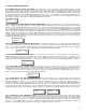
Extra Relays: If the target application will require more than eight relay contacts, optional remote relay modules (M/N RRM-8) can be
purchased and attached to the system wiring run. Each module provides eight only S.P.D.T. dry contact relays rated 5 amps @ 240 VAC.
The extra relays can be programmed from the system codes. The RRM-8 can be remotely installed and wired directly into the BUS wiring. It
receives it’s power from the PDC. After installation, double check wiring then refer to page-28, code “3222” for specific instructions to set up
this device. This procedure MUST be followed or the PDC will not recognize this device.
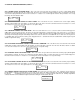
Analog Output Signal: Optional analog output modules (M/N RAO-8) can be purchased and attached to the system wiring run. Each module
provides eight only individual analog output signals 4 - 20 mA. The analog outputs can be programmed from the system codes. (Consult
factory for details). The RAO-8 can be remotely installed and wired directly into the BUS wiring. It receives it’s power from the PDC. After
installation, double check wiring then refer to page-28, code “3232” for specific instructions to set up this device. This procedure MUST be
followed or the PDC will not recognize this device.
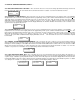
Remote Annunciation: This peripheral device (M/N RAP-128) provide the user with a remote display, alarm lights and audible alarm. It can be
installed remotely from the PDC and wires directly into the BUS wiring system. It receives it’s power from the PDC through the BUS wiring.
When the PDC controller goes into alarm and the audible is activated, the audible on the remote annunciator is also activated. The user can
use the local silence button to silence it. Silencing the local audible does not affect the audible alarm on the PDC controller. This device has
no digital ID and therefore will display data received from the PDC without any setup procedure.
10.0 ADDING ANALOG TRANSMITTERS TO AN EXISTING DIGITAL SYSTEM
If the user wishes to add analog transmitters (AST series) to an existing system that has only digital transmitters (DST series) connected, the
following procedure must be followed:
1) Open all the doors of all DST digital transmitters.
2) At the PDC controller, Input code “3212” and the display will indicate “CH-1 ID #9”. Using the “1” button, scroll down to ID code #1. Press
“2” button to accept this. The display will automatically scroll to the next channel (channel-2) and display the assigned ID number which
should be “10”). At this point, the user must walk around and push the auto cal button on each DST digital transmitter in the order that he
wishes them to appear in the scrolling display.
11.0 MODEL AND PART NUMBERS
MODEL NUMBERS DESCRIPTION
PDC-A0808 Analog system with 8 inputs and 8 relays
PDC-D1608 Digital system with 16 inputs and 8 relays
PDC-D3208 Digital system with 32 inputs and 8 relays
PDC-D6408 Digital system with 64 inputs and 8 relays
PDC-D9608 Digital system with 96 inputs and 8 relays
PDC-D12808 Digital system with 128 inputs and 8 relays
RPS-24V Switching power supply module c/w wall mount enclosure (Maximum 1.7 amp current load each)
RRM-8 Relay module c/w wall mount enclosure (8-relays each)
RAO-8 Analog output module c/w wall mount enclosure (8-analog outputs each)
PART NUMBERS DESCRIPTION
PDC-EN Standard metal locking enclosure c/w Lexan label (does not include audible alarm or silence
push-button)
PDC-LEDM LED digital display module
PDC-LCDM LCD digital display module
PDC-SPSB Switching power supply circuit board
PDC-MBA Main analog mother board circuit board
PDC-MBD Main digital mother board circuit board
DST-ETB Electrochemical digital transmitter circuit board
DST-STB Solid-state digital transmitter circuit board
NOTE: Consult factory for a more extensive list of part numbers.