
Specifications


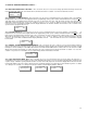

30
8.0 CALIBRATION OF SENSOR / TRANSMITTERS
Frequency: All sensors require regular calibration maintenance to ensure accuracy and indeed to confirm that they have not expired.
Electrochemical sensors installed in applications such as parking facilities should be gas calibrated a minimum of once per year. A frequency
of once every six months is preferred.
Sensors installed in applications that must specially meet the need for Occupational Health & Safety standards should be gas calibrated once
every six months. These sensors should be gas tested once per month with a known concentration of target gas.
Analog: Refer to calibration details provided in the installation/operation manual supplied with the AST analog transmitter.
Note: All sensors are shipped pre-calibrated from the factory. If the end user absolutely wants to perform a calibration on the digital sensors,
then follow the “manual-cal” procedure on the next page.
Digital: The DST transmitter is equipped with an “Auto Cal” feature to simplify the calibration procedure. For proper calibration, the correct
span gas concentration value must be entered into the DST (code “1222”). This is accomplished at the PDC controller.
To change this value, depress push-button #1 to decrement the value or push-button #3 to increment the value. Holding the push-button will
scroll the numbers quickly. Once the correct value is achieved, depress push-button #2 to accept the value and take you to the next active
channel. Repeat this procedure for all active channels.
NOTE-1: The “ Auto-Cal” function will not activate if a background gas level above “5” is detected.
NOTE-2: The green power LED showing through the door of the DST is a multi-function, tri-colour LED. Different colours are utilized for
different functions.
At the transmitter, open the enclosure door and ensure the amber “Link” LED is illuminated. Prepare for “Auto-Cal” by applying zero air to the
sensors for approximately 2-minutes or inserting the calibration adapter plug with both caps attached for approximately 5-minutes, to ensure
sensor is not responding to any background gas. The first step in the auto calibration function is “Auto-Null”.
Next, depress the “Auto-Cal” push-button. The green LED (LED-2) located internally (upper left side of board) on the DST circuit board will
illuminate and the green power LED will begin to flash amber.
At this point, begin flowing span gas. When the DST recognizes the gas flow, the internal green LED is illuminated and the front green LED
will flash alternately amber and red. After a 3-minute timed sequence, the outer LED will illuminate as solid red at the alarm level set for that
channel and the transmitter will save the calibration data and resume normal operation. During the calibration procedure, the DST will not
transmit the gas value information to the PDC.
Do not press the “Auto-Cal” push-button again unless you want to abort the calibration function. In the event that the push-button is pressed
again, the calibration function will be aborted, however, the new null value will be retained and entered. The new null value will not affect any
previous saved calibration values.
The digital display for the channel being calibrated on the PDC controller will not show any numbers until the auto-cal process is complete.
Depending on the concentration of calibration span gas utilized, the PDC controller may indicate an alarm condition immediately after
completion of the auto-cal function as the sensor recovers from the exposure to span gas.
NOTE-1: “IMPORTANT” When calibrating solid-state sensors only, remember to humidify the span gas. CETCI calibration kits contain a
humidification chamber specifically for this purpose. Remove the sponge from the chamber and wet it thoroughly with water. Wring out the
excess water so the sponge is quite damp and place the sponge back into the chamber. Connect to cylinder regulator and flow span gas as
per instructions on previous page. If the monitored environment is in a very humid climate, simply do not wring out as much water, leaving the
sponge wetter. DO NOT USE THE HUMIDIFICATION CHAMBER WHEN CALIBRATING ELECTROCHEMICAL SENSORS.
NOTE-2: If the DST does not see gas for more than 60 seconds, the auto-cal function will automatically terminate and not affect any
previous calibration performed.
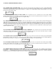
NOTE-3: The sensors utilized in the DST solid-state version have a heated element. If the sensor burns out, a fault condition is created at
the PDC controller. As a quick trouble-shooting reference, the solid-state sensor DST circuit board has a green LED (as indicated in the pho-
to on page-21) which goes out. This indicates the fault condition was caused by a burned out sensor element.