
Specifications


29
7.4 OUTPUT CODE DESCRIPTIONS, CONT’D…..
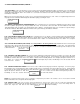
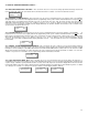
3332 “MESSURE ANALOG INPUT VOLTAGES”: This code allows the user to measure the analog input without having a external volt
meter To achieve this, input code “3332” and the LCD looks like the box below. Use button “3” to increment channels to monitor.
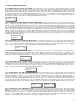
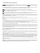
3123 “INITIALIZE SYSTEM DEFAULTS”: This menu item resets the system configuration back to the original setup. It should not be
attempted unless the user has been thoroughly trained in the programming of PDC system software and understands the consequences. The
entire PDC must be re-programmed after using this menu code. To achieve this, first enter “1323” the unlock code then enter “3123” and the
display will look like the box below. Use the ‘1” or “3” button to select “yes” or “no”. Use the “2” button to scroll out of this menu function. If the
user selects yes, the system will be reinitialized and the display will indicate “No Channels Enabled”. This indicates to the user that the entire
system must be re-programmed before use.
1113
“FACTORY DEFAULTS”: This menu item resets the system configuration back to the factory defaults. It should not be at-
tempted unless the user has been thoroughly trained in the programming of PDC system software and understands the consequences. The
PDC must be re-programmed after using this menu code. To achieve this, first enter “1323” the unlock code then enter “1113” and the display
will look like the box below. Use the ‘1” or “3” button to select “yes” or “no”. Use the “2” button to scroll out of this menu function. If the user
selects yes, the system will be reinitialized and the display will indicate “CH 001 OK”. This will be the same as if a new Firmware ship had
been installed.
3311
“ENABLE / DISABLE REMOTE DISPLAY MODULE”: This code allows the user to add one or more remote display module(s)
(Remote Annunciator) to the PDC BUS system. The remote annunciator simply reproduces the information indicated on the PDC LCD and
LED lights as well as activating it’s own audible alarm when the PDC main internal audible alarm is activated. The user can silence the audible
with the on board silence push button. To achieve this, input code “3311” and the LCD looks like the box below. Use button “1” to select “No”
or button “3” top select “Yes”. Push button “2” to accept the change and the LCD indicates “Finished”.
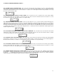
3331 “WDT (WATCH DOG TIMER) TEST”: This code allows the user to view information about specific problems that may have oc-
curred with the PDC system. It also displays a power counts indicating if the microprocessor has experienced any fluctuations from brown outs
or power outages. It identifies specific problems that have occurred. To view this, input code 3331 and the display will look like the box below.
It then quickly indicates the power count box then the last box is indicated asking the user if they want to test the Watch Dog Timer. Use button
“3” to change to Yes or button “1” to change to No then press button “2” and the display indicates ‘finished”.
SYSTEM ERROR
Watch Dog Error
SYSTEM ERROR
Power Count 10
SYSTEM ERROR
Test WDT No
CH 001 Menu 3332
Voltmeter 0.01
Menu 3311
Remote Dply No
System Reset
Continue NO
System Reset
Continue NO