
Specifications


27
7.4 OUTPUT CODE DESCRIPTIONS, CONT’D…..
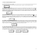
2333 “STROBE OUTPUT ACTIVATION LEVEL”: This code controls the gas alarm level at which the “strobe” output (24VDC @ 400
mA maximum) is activated (upper left side of main board). The choices are a universal Low, Mid or High gas alarm. To achieve this, input code
‘2333” and the display will look like the box below. Use button “1” or button ‘3” to scroll through the selections then push button “2” to accept
the change. The LCD indicates “Wait”.
2123 “ACTIVATING STROBE OUTPUT AT FAULT ALARM”: This code allows the user to determine if the strobe output (24VDC)
should be activated with a PDC fail condition. To achieve this input code “2123”. The LCD looks like the box below. Use button “1” to select
‘No” or button ‘3” to select “Yes”. Next, push button “2” to accept the change
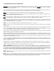
3131 “ON-BOARD AUDIBLE ACTIVATION LEVEL”: This menu item allows the user to select the alarm level which will trigger the
audible alarm on the front enclosure door. The choices are low, mid or high alarm. To achieve this, input “3131” and use the “1” or “3” button to
decrement or increment through the choices. Press the “2” button to exit this menu item. Once the audible alarm has been activated, it can be
silenced by momentarily pressing the “Acknowledge” button of the enclosure front door. The audible will cease to make noise as long as there
is a qualified alarm present. Once the alarm(s) have dropped below the activation threshold, the audible will be activated again. System
default is to high alarm setting.
2122 “ACTIVATING THE INTERNAL AUDIBLE ALARM AT FAULT CONDITION”: This code allows the user to determine if the internal
audible alarm should be activated with a PDC fail condition. To achieve this input code “2122”. The LCD looks like the box below. Use button
“1” to select ‘No” or button ‘3” to select “Yes”. Next, push button “2” to accept the change.
3133 “AUXILIARY OUTPUT ACTIVATION LEVEL”: This code controls the gas alarm level at which the auxiliary output (24VDC @ 400
mA maximum) is activated. The choices are a universal Low, Mid or High gas alarm. To achieve this, input code ‘3133” and the display looks
like the box below. Use button ‘1” or button “3” to scroll through the choices. Push button “2” to accept the change.
2121 “ACTIVATING AUXILIARY OUTPUT AT FAULT ALARM”: This code allows the user to determine if the auxiliary output (24VDC)
should be activated with a PDC fail condition. To achieve this input code “2121”. The LCD looks like the box below. Use button “1” to select
‘No” or button ‘3” to select “Yes”. Next, push button “2” to accept the change.
3313
“ENABLE AUXILIARY OUTPUT FOR SYSTEM ALARM”: This menu code is used to set the “Aux” (auxiliary) output terminal to
provide 24VDC to activate an external alarm to act as a PDC system alarm. This will be activated in the event that the firmware “watchdog”
has already automatically reset the microprocessor three times because of a problem. On the fourth time, the auxiliary output will be
activated. Maximum current available through this terminal for driving an external alarm is 400 mA.
BUZ 001 Menu 2122
Fault Act No
AUX Menu 2121
Fault Act No
ST MENU 2333
Strobe Lvl High
BUZZ Menu 3131
Buzzer Lvl HIGH
Aux Menu 3133
Aux Act Lvl High
ST 001 Menu 2123
Fault Act No
AUX001 Menu 3313
Aux=WDT Ext Yes