
Specifications


26
7.4 OUTPUT CODE DESCRIPTIONS, CONT’D…..
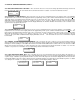
3221 “RELAY ENABLE / DISABLE”: This code allows the user to enable or disable a specific relay. The choices are “ Yes” or “ No” .
To achieve this, enter “3221” and the display will look like the box below. Use the “1” or “3” button to select ‘No” or “Yes” then push the “2”
button to scroll to the next relay. If you are not configuring all the relays, use the “2” button to scroll to the end of this menu and the display
will indicate “Finished”.
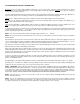
3132 “RELAY TOGGLE”: This menu item allows the user to toggle each of the relays manually. The user simply enters “3132” and
the display will look like the box below. NOTE: When this code is first entered, the system automatically de-energizes all relays. The user
must first re-energize all relays prior to the toggle function. To achieve this, push the “2” button and select “energized”, then use the “3” to
scroll to the next relay and once again push the “2” and so on until you have re-energized all eight relays. Once you have re-energized relay-
8, push the “1” button to scroll back to relay-1.
2332 “RELAY FAULT ACTIVATION”: This menu item is used to select the type of faults which will activate each relay. There are 4
choices in this menu; “Sense”, “All”, “All+” or “None”. The “Sense” mode allows any channel, listed in menu item 2113, which goes into fault
to cause the relay to activate. In the “All” selection, any channel that is in fault condition will cause the relay to activate. In the “All+” mode,
any channel which is in fault or a system fault will cause a specific relay to activate. The maximum number of channels that can be associat-
ed with any one relay is 32. To achieve this, enter “2332” and the display will look like the box below. Use the “1” or “3” button to scroll down
or up through the choices then push the “2” button to scroll to the next relay. If you are not configuring all the relays, use the “2” button to
scroll to the end of this menu and the display will indicate “Finished”.
2113 “SETTING FAULT ALARM CHANNELS FOR RELAY MONITORING”: In this menu item the user can select the channel(s) which
will be monitored for fault alarm conditions for each relay. Any channel included in this list, which goes into fault alarm will cause a specific
relay to activate as long as the menu item “2331” has been set to “Sense”. The maximum number of channels that can be associated with
any one relay is 32. The choices are from 1 to 128 or “none”. To achieve this, enter “2113” and the display will look like the box below. The
first number displayed indicates the first channel on the monitored list for that relay. Pressing “2” repeatedly allows the user to view which
channels are listed for monitoring by each relay. When the display indicates “done”, this means you are at the end of the list. If you wish to
add more channels, use the button “3” to increment to that channel number. Once you have added all the channels to be associated with that
relay, press button “2” until the display once again indicates “done” then press button ‘2” once more to scroll to the next relay. Repeat this
procedure until all desired channels have been associated with specific relays. At the last relay (8), press button ‘2” to scroll out of the menu
and the display will indicate “Finished”.
3222 “EXTERNAL RELAY MODULE CODE ID ASSIGNMENT”: This code allows the user to add a remote relay module to a PDC sys-
tem by setting the digital ID (address) so the PDC will recognize it. The device must be installed, wired and powered up to accomplish this.
To achieve this, input code “3222” and the LCD will look like the box below. At this point, someone must walk over and push the small white
button located on the bottom left corner of all the remote relay module board. The ID code-1 indicate on the LCD will automatically advance
to “2”. If more than one relay module has been installed, walk to the next relay module and press the small white button on it. This causes the
ID code to advance to “2”. Repeat this procedure for each installed relay module. Next, use the “1” button to scroll down to “Done” on the
LCD then push the “2” button. The LCD indicates ‘Wait” while it acknowledges the new ID coded device(s).
NOTE: If an external relay module is attached to the system, it must be activated within the PDC system before it will respond to
any communication from the PDC. Reference section 9.0, page-31 for more details.
RL 001 Menu 2113
Mon Channel 1
RL 001 Menu 3221
Enabled? Yes
RL 001 Menu 3132
Relay Ctrl off
RL 001 Menu 2332
Fault Act All
RL 001 Menu 3222
ID code 1